FRONT MOUNTING BRACKET MUST BE INSTALLED TO A
STRUCTURAL SUPPORT (STUD) ON THE HEADER WALL.
FAILURE TO DO SO COULD CAUSE SENSING SYSTEM TO
MALFUNCTION, RESULTING IN ENTRAPMENT, INJURY OR
DEATH. REINFORCE HEADER IF NECESSARY USING A WOOD
STUD OR ANGLE IRON AND LAG SCREWS (NOT PROVIDED).
WARNING
STEP 1: Mounting the Front Bracket —
Sectional Doors and One-Piece Doors with Track (For
One-Piece Doors without track see Step 1A, next): Mark a
vertical centerline on the header above the door. By
manually raising the door, determine the high arc of the
door’s travel (see illustrations on page 4) and using a level,
transfer this measurement to the header (see illustration at
left). Draw a horizontal line, crossing the previously
drawn centerline, at this point. Install the Front Mounting
Bracket securely with the lag screws as illustrated below.
If necessary, reinforce the header with steel angle iron or
wood to ensure a secure mount.
STEP 1A: Mounting the Front Bracket — One Piece
Doors Without Track: Mark a vertical centerline on the
header above the door. Manually raise the door to its high arc
position and temporarily clamp in that position. With the door
in this high arc position, measure the distance from the top of
the door to the floor (see figure at left). Subtract the actual
door height from the high arc distance to the floor. This is the
high arc rise of the door. Unclamp and close the door. Using
the table below, draw a horizontal line at the appropriate height
above the door to intersect with the vertical centerline.
Mount the Front
Mounting Bracket
securely with lag
screws as shown in the
figure below. If
necessary, reinforce the
header with steel angle iron or wood to ensure a secure mount.
104369
C: INSTALLING THE OPERATOR
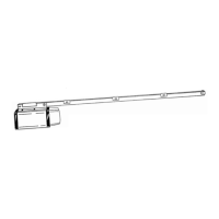
STEP 2: Raise the Tee Rail so that the Front Idler Bracket and
Front Mounting Bracket align. Insert bolt and tighten nut loosely for
now. Later in the installation, this nut must be tightened securely.
STEP 3: Sectional Doors and One
Piece Doors with Track: Raise the
opener and rest the Power Unit
on a ladder or other sturdy
support. Open the
door to the full open position. Allow 2" of space between the
Tee Rail and the top section of the door (as shown in the
illustration on the top of page 7, left).
STEP 3A:
One Piece Doors without Track:
Raise the opener and rest the power unit on a ladder or
other sturdy support. Open the door to the high arc
1/2” Above
High Arc Mark
High Arc Mark
Lag
Screws
Vertical
Centerline
Cardboard or Cloth to
protect the Housing
Wall Mounting
Bracket
1/4” x 4”
Hex Head Bolt
Wall Mounting Bracket
Nut
Front
Wall
Bracket
110049
110050-1
HIGH ARC HORZ. LINE
4 INCHES 8 INCHES
4 TO 8 INCHES 13 INCHES
8 TO 12 18 INCHES
HORIZONTAL
LINE
VERTICAL
CENTERLINE
Header Bracket
Bracket Distance Above
Floor (See Chart)
Highest
Point
of Travel
Measure
Distance
to Floor
Garage
Floor
Door
104370
6