7 . ACCESSORIES AND OPTIONS
7.20
Challenger MT500B EU
7.5.4 - Use
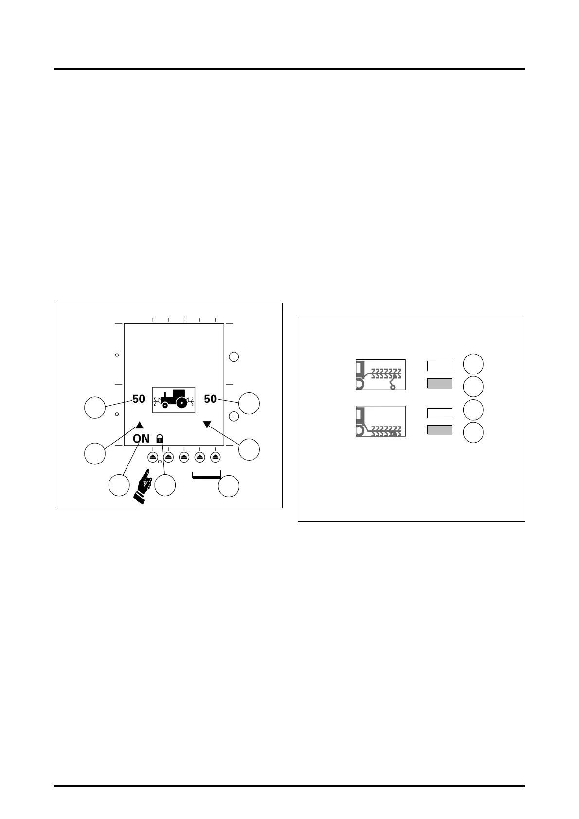
In the drop-down menu select -DUAL- and
-FRONT CTRL-; a new display appears in the lower half of
the screen :
• Ref.15: Position of the rear linkage control in %
• Ref. 16: Lifting / lowering indicator light for rear imple-
ment
• Ref.17: ELC status (Locked / Unlocked)
• Ref.18: Front Dual Control status -ON- (activated) /
-OFF- (deactivated).
• Ref.19: Front implement lifting / lowering indicator light.
• Ref.20: Front linkage position in %.
To use the DUAL once the data has been stored and on
each start up, it is necessary to unlock the console, the joy-
stick (if fitted) and to place the Datatronic in the -ON- posi-
tion, ref. 18, using the corresponding key.
NOTE: If the value is incorrect (e.g.: front-to-rear imple-
ment length is too high), or if you trigger the furrow
start or end phase but halt before this phase is entirely
completed, the rear plough that is still in the high posi-
tion will change to the low position after eight seconds.
In static mode, if the Dual is active, you can place the im-
plements on the ground (front and rear) in two different
ways:
1. Place the front implement on the ground by using its
spool valve lever and the rear implement using selec-
tor switch (Q).
2. Place selector switch (Q) in the lowering position: the
front lift control lowers then 8 seconds afterwards the
rear lift control lowers.
To activate the road transport mode or adjust the use po-
sitions, it is necessary to deactivate the DUAL function
(OFF position).
NOTE: For the best use of FRONT DUAL it is recom-
mended that the suspended front axle function be
deactivated.
7.6 - TRAILED IMPLEMENT CONTROL (TIC)
7.6.1 - General
TIC is a system that controls the trailed rear implement on
the swinging drawbar. In working mode, the wheel slip, im-
plement depth and force applied to the swinging drawbar
are analysed by the calculator that varies the height of the
implement. However, in versions without draft control,
only the wheel slip and depth button act upon the height of
the implement. The information required for the system is
acquired by 3 sensors:
1. swinging drawbar draft sensor (optional),
2. position sensor on the trailed implement,
3. ground speed radar.
The information is then processed by the DATA 2 onboard
computer and the electronic linkage control calculator that
controls an electrohydraulic spool valve.
The TIC is at presently available only on tractors equipped
with LOAD SENSING hydraulics.
7.6.2 - Description of the adjustment screen
(See section 7.4)
Press key 2 or 3 (Fig. 20), the drop-down menu appears.
Select -TRAIL ADJ- above -DUAL-. Two new symbols are
displayed (Fig. 24):
• Ref. A to B: This information is used to adapt the height
of the implement to the “headland furrow” mode.
• Ref. C to D: This information is used to adapt the depth
of the rear implement to “working” mode. To select
one of the display windows, use keys 6-1 and 6-2 (Fig.
23).
V 973
Fig. 23
19
20
16
15
1718
12
6
217
217
37
37
A
B
C
D
V 974
Fig. 24
 Loading...