Inside
Property
Outside
Property
ENTRAPMENT PROTECTIONGATE CONSTRUCTION & SITE PREPARATION INSTALLATION OVERVIEW
Inside
Property
Outside
Property
Inside
Property
Outside
Property
CONTACT SENSORS (EDGE SENSORS)
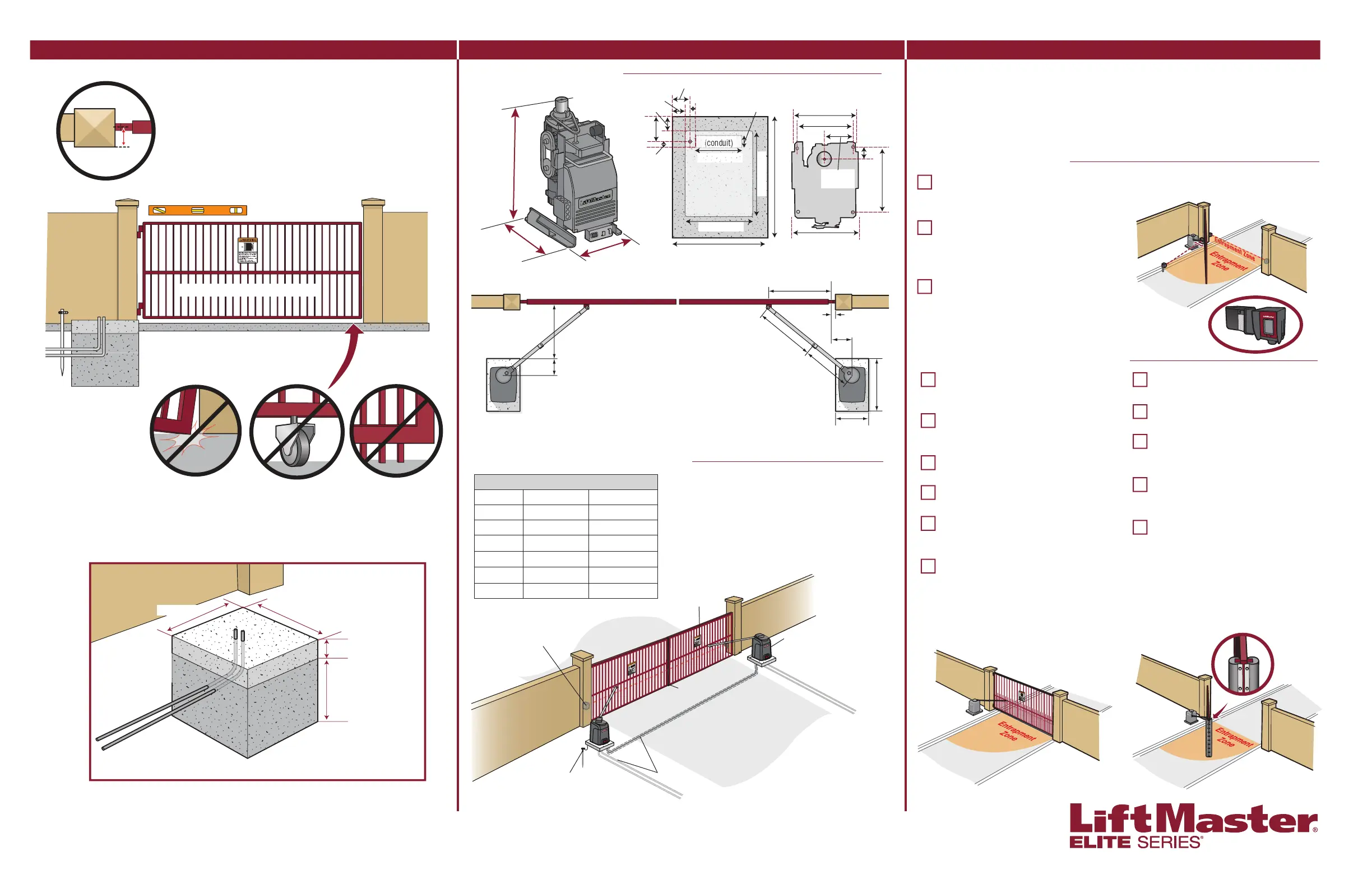
STANDARD DUAL GATE INSTALLATION
OPERATOR DIMENSIONS
Concrete Pad
6" (15.2 cm) Above Ground
OPERATOR POWER SOURCE
Wire Gauge 120 Vac 240 Vac
14 130 feet (40 m) 260 feet (79 m)
12 205 feet (62 m) 410 feet (125 m)
10 325 feet (99 m) 650 feet (198 m)
8 520 feet (158 m) 1040 feet (316 m)
6 825 feet (251 m) 1650 feet (503 m)
4 1312 feet (400 m) 2624 feet (800 m)
NOTE: Use copper conductors ONLY.
11" (27.9 cm)
MOUNTING FOOTPRINT
46" (116.8 cm)
2"
(5.1 cm)
35.5"
(90.2 cm)
28" (71.1 cm)
24"
(60.9 cm)
25" (63.5 cm)
24" (60.9 cm)
5.5" (13.97 cm)
27.66"
(70.3 cm)
Water Tight Conduit (Not provided) NOTE: Power and control
wiring MUST be run in separate conduits.
Earth Ground Rod
Check national and local codes
for proper depth
Warning Sign
Photoelectric
Sensors
Edge Sensor
NOTE: Wired connection in a dual gate setup is optional.
Operators can be setup for wireless dual gate communication.
Operator
This operator contains an inherent (internal) entrapment protection system and REQUIRES
the addition of a LiftMaster external monitored entrapment protection system (non-contact
photoelectric sensor or contact edge sensor) for EACH entrapment zone prior to gate movement.
An entrapment zone is every location or point of contact where a person can become entrapped
between a moving gate and a stationary object. Your application may contain one or many
entrapment zones. System includes six monitored entrapment protection inputs capable of
covering all entrapment zones. Use only LiftMaster approved entrapment protection devices.
NON-CONTACT SENSORS
Model LMWEKITU
LiftMaster Monitored Wireless Edge Kit
(Transmitter and Receiver)
Model LMWETXU
LiftMaster Monitored Wireless Edge
Transmitter
Model L50
Large Profi le Monitored Edge
(82 ft. roll)
Model L50E
Large Profi le Ends Kit (pair, pack of 10)
Model L50CHP
Channel for both Large and Small Profi les -
PVC (8 ft., pack of 10)
Model L50CHAL
Channel for both Large and Small Profi les -
Aluminum (10 ft., pack of 8)
Model LMTBU
LiftMaster Monitored Through Beam Photoelectric
Sensor
Model LMRRU
LiftMaster Monitored Retro-Refl ective Photoelectric
Sensor
NOTE: LMRRU is provided with the operator
Model CPS-UN4
LiftMaster Commercial Protector System
®
Model S50
Small Profi le Monitored Edge (82 ft. roll)
Model S50E
Small Profi le Ends Kit (pair, pack of 10)
Models L504AL, L505AL, and L506AL
Large Profi le Edge - Aluminum Channel
(4 ft, 5 ft, 6 ft)
Models S504AL, S505AL, and S506AL
Small Profi le Edge - Aluminum Channel
(4 ft, 5 ft, 6 ft)
Model ETOOL
Edge Cutting Tool
Inside
Property
Outside
Property
INSIDE PROPERTY
Maximum gate weight/length:
1200 lbs. (544.3 kg)/12 foot (3.7 m)
800 lbs. (362.9 kg)/16 foot (4.9 m)
600 lbs. (272.2 kg)/18 foot (5.5 m)
Earth Ground Rod
Check national and local
codes for proper depth
High and Low Voltage UL approved
conduit. Power and control wiring MUST
be run in separate conduits
Warning Placard on both sides of gate.
Gate MUST be level. Gate and gate post MUST be plumb.
There should only be a
maximum of 4" (10.2 cm)
from the center of the hinge
to the edge of the post or
column. If the distance is
greater than 4" (10.2 cm)
entrapment protection for this
area is required.
Gate MUST have a
smooth bottom edge, no
protrusions should exist.
Remove ANY/ALL wheels
from the bottom of gate.
Gate MUST NOT
hit or drag across
ground.
Gate MUST swing freely and be
supported entirely by its hinges.
24" (61 cm)
28" (71 cm)
18.77"
(47.7 cm)
14.8"
(37.6 cm)
4.5" (11.4 cm)
1" (2.5 cm)
4" (10.2 cm)
6.5"
(16.5 cm)
1.5"
(3.8 cm)
10" (25.4 cm)
3" (7.6 cm)
(conduit)
15" (38.1 cm)
20" (50.8 cm)
28" (71.1 cm)
13.6" (34.5 cm)
12.2" (31 cm)
6.1"
(15.5 cm)
2.49"
(6.3 cm)
14" (35.6 cm)
14.82" (37.6 cm)
10" (25.4 cm)
29.5"
(74.93 cm)
For a gate operator utilizing a contact sensor, if the bottom
edge of a swing gate is greater than 6 inches (15.2 cm) above
the ground at any point in its arc of travel, one or more contact
sensors shall be located on the bottom edge.
If utilizing a contact sensor as entrapment protection, one
or more contact sensors shall be located on the inside and
outside leading edge of a swing gate.
Below the frost line. Check
all national and local codes.
Minimum of 24" (61 cm)
recommended in regions
with no frost line.
Entrapment protection is required for the area between the
open gate and the operator. Entrapment protection is
required for the area between the gate and the curb.
For more information:
www.devancocanada.com
or call toll free at 855-931-3334
 Loading...