2
CONTENTS OF THE CARTON
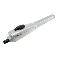
(1) Wing gate actuator unit for left-hand installation and/or
(2) Wing gate actuator unit for right-hand installation
(3) Mounting brackets
(4) Installation accessories pack
Hinge pins with circlips (2)
Emergency opening handle (1)
Capacitor (1)
(5) Instruction manual
(6) Warning light kit
(7) IR Sensors
(8) Transmitter
(9) Control box
PRODUCT DESCRIPTION -
HC300R, HC300L, HC400R+L
Scope of application: Motorized opening and closing of
gates.
Illustration 3 shows a dimensional outline of the actuator arms.
The actuator units are suitable for use with single and double
gates. For HC300, the maximum gate width may not exceed
2.5 m and for HC400 it may not exceed 3.0 m. Maximum
weight 300 kg per gate.
For design reasons, all wing gate actuator units, operating
with linear movement, must follow the given installation
dimensions.
Some gate or post types may require recessing
of the post or use of the longer stroke actuator, in order to
achieve the installation dimensions.
Technical data
HC300 HC400
Power supply 230V - 50Hz 230V - 50Hz
Capacitor 10 µF 10 µF
Current drawn 1.5 A 1.5 A
Power 350W 350W
Opening angle 110° max 110° max
Max. cycles/hours 20 20
Force 200kg 200kg
Max. actuator unit length 97cm 112cm
Motor thermal overload switch 140 °C 140 °C
Rated weight of motor 6.5kg 7kg
Dimensions see fig.3 see fig.3
Speed 1.5cm/s 1.5cm/s
IP Rating (motor) IP54 IP54
INSTALLATION -
Preparations
Before installation, please check contents of packaging.
Please refer to Illustration 1.
Ensure your gate equipment functions correctly.
Please keep in mind, that you will need parts not included in
the packaging (tubes, cable, screws, rawlplug and so on)
Installation preparation
As an example, Illustration 4 illustrates installation with a
stone or steel post construction. The installation dimensions
for the gate actuator unit are dependant on the fastening
points of gate to post.
llustration 5 shows the meaning of installation dimensions A
and B. The measurements chosen also
determine the opening
and closing times and the maximum opening angle of the gate.
Sample for A=14cm and B=14cm (approx. 90
0
)
1
INHALT DES KARTONS
(1) Drehtorantrieb für Linkseinbau und/oder
(2) Drehtorantrieb für Rechtseinbau
(3) Scharnierteile zur Befestigung
(4) Montagezubehörbeutel
Befestigungsbolzen mit Sicherheitsringen (2)
Notentriegelung (1)
Kondensator (1)
(5) Montageanleitung
(6) Warnlampe
(7) Sicherheitslichtschranke
(8) Handsender
(9) Steuerung
PRODUKTBESCHREIBUNG -
HC300R, HC300L, HC400R+L
Bestimmungsgemäßer Gebrauch: Motorisiertes Öffnen und
Schließen von Toren.
Abbildung 3 zeigt die Abmessungen der Antriebe.
Die Antriebe sind für ein -und zweiflügelige Tore geeignet Die
Breite eines Torflügels darf beim HC300 nicht über 2,5 m,
beim HC400 nicht über 3,0 m betragen. Maximales Gewicht
300kg pro Flügel.
Bauartbedingt müssen bei allen Drehtorantrieben, die mit
linearer Bewegung arbeiten, bestimmte Einbaumaße
eingeghalten werden.
Je nach Beschaffenheit des Pfeilers
oder Torflügels können diese Maße nur durch Ausparungen
am Pfeiler oder durch Verwendung von Antrieben mit
größerem Hub erreicht werden.
Technische Daten
HC300 HC400
Netzanschluß 230V - 50Hz 230V - 50Hz
Kondensator 10 µF 10 µF
Stromaufnahme 1.5 A 1.5 A
Leistungsaufnahme 350W 350W
Öffnungswinkel 110° max 110° max
Max. Zyklen/Std. 20 20
Zugkraft 200kg 200kg
Max. Antriebslänge 97cm 112cm
Motorthermoschutz 140 °C 140 °C
Nettogewicht Motor 6.5kg 7kg
Abmessungen siehe Abb..3 siehe Abb..3
Geschwindigkeit 1.5cm/s 1.5cm/s
IP Werte (Motor) IP54 IP54
MONTAGE -
Vorbereitungen
Überprüfen Sie bitte vor der Montage den Inhalt der
Verpackung auf Vollständigkeit. Siehe Abbildung 1.
Stellen Sie die einwandfreie Arbeitsweise Ihrer Torvorrichtung
sicher.
Bedenken Sie, daß Sie noch Material benötigen, daß
sich verständlicherweise nicht in unserem Lieferumfang
befinden kann (Leerrohr, Kabel, Schrauben, Dübel etc.)
Montagevorbereitungen
Beispiele für eine Montage an Mauerwerk oder Stahlpfeilern
sind in Abb. 4 dargestellt. Die Montagemaße eines Torantriebes
sind von der Befestigung des Torflügels am Pfeiler abhängig.
Abb. 5 zeigt die Bedeutung der Einbaumaße A und B. Die
gewählten Maße bestimmen gleichzeitig die Öffnungs- und
Schließzeit und den maximalen Öffungswinkel eines Torflügels.
Beispiel für A=14cm und B=14cm (für ca. 90
0
)
1
2
2
3
3
4
6
4 6
D
GB
 Loading...