Do you have a question about the Chamberlain Liftmaster BMT5011 and is the answer not in the manual?
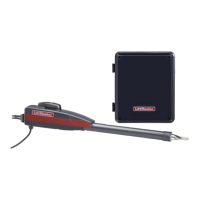
Details about the motor type, horsepower, speed, voltage, and current.
Information on transformer, control station, wiring type, and limit adjustment.
Details on drive reduction, shaft speed, door speed, brake, and bearings.
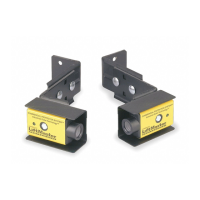
Information on disconnect, sensing devices, and safety recommendations.
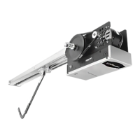
Physical characteristics including hanging weight and diagrams.
Critical warnings regarding door balance, tension, and potential injury.
Instructions for assembling the operator track and installing spacers.
Steps to position and attach the track assembly to the powerhead.
Procedure for attaching the trolley carriage and adjusting chain tension.
Steps for locating and mounting the header bracket above the door opening.
Procedure for attaching the operator track to the header bracket and aligning it.
Methods for supporting the operator from the ceiling, including brace types.
Steps to attach the straight and curved door arms to the trolley and door.
Compatibility and mounting of sensing edges for safety.
Notes on connecting sensing edges via take-up reel or coil cord.
Steps for adjusting open and close limit nuts for proper door travel.
Warning about electrical hazards when manually moving limit nuts.
Instructions for connecting the power supply, ensuring correct voltage and grounding.
Information on conduit knockouts for power and control wiring.
Critical warnings about disconnecting power, grounding, and qualified personnel.
Explanation of standard C2 and B2 wiring configurations.
Notes on non-standard wiring and using supplemental diagrams.
Guidelines for mounting the control station and associated safety warnings.
Instructions for mounting radio receivers and using radio controls.
Connecting other control devices like loop detectors or card keys.
Using an external interlock switch to disable operator control.
Warning regarding proper clutch adjustment for operator function and life.
Explanation of the A.R.S. feature and its entrapment protection.
Diagram identifying components of the friction clutch system.
Instructions and diagrams for disconnecting and reconnecting the door arm.
Warning to avoid being struck by the door arm when using the emergency disconnect.
Key notes before operating and testing controls and safety devices.
Warning about keeping hands clear and disconnecting power during testing/servicing.
Diagram illustrating the components of the solenoid brake system.
Schedule for checking and lubricating drive chain, sprockets, clutch, belt, and fasteners.
| Type | Belt Drive |
|---|---|
| Horsepower | 1/2 HP |
| Voltage | 120V |
| Speed | 7 inches per second |
| Remote Control | Yes |