1
COMMERCIAL PROTECTOR SYSTEM
®
MODELS CPS-U AND CPS-UN4
To prevent possible SERIOUS INJURY or DEATH from a closing
gate or door:
• Entrapment protection devices MUST be installed per the
operator owner's manual.
• Be sure to DISCONNECT POWER to the operator BEFORE
installing the photoelectric sensor.
• The gate or door MUST be in the fully opened or closed
position BEFORE installing the LiftMaster Monitored
Entrapment Protection device.
• Correctly connect and align the photoelectric sensor.
• Install the photoelectric sensor beam NO HIGHER than 6"
(15 cm) above the fl oor for door and 27.5" (69.8 cm) above
grade for gate operators.
APPLICATION
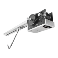
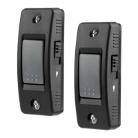
NOTE: The images throughout this manual are for reference and your product may look different.
The CPS-U and CPS-UN4 are suitable for use with LiftMaster Commercial Door Operators (Medium Duty Logic, Logic 3 or 4, models
FDC, FDCL, FDO, and LGE). The CPS-UN4 may also be used with gate operator (Series models: CSL24V, CSW24V, RSW12V, RSL12V,
LA400, LA412, and LA500). The CPS-UN4 is suitable for use in applications where the photoelectric sensors will be exposed to moisture.
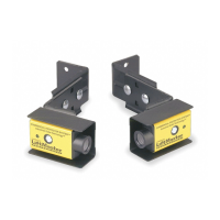
These photoelectric sensors are LiftMaster Monitored Entrapment Protection (LMEP) devices.
THE PROTECTOR SYSTEM
®
IMPORTANT INFORMATION ABOUT THE PHOTOELECTRIC SENSOR
Be sure power to the operator is disconnected.
When properly connected and aligned, the photoelectric sensor will detect an obstruction in the path of its invisible light beam. If an
obstruction breaks the light beam while the door/gate is closing, the operator will stop and typically reverse to the full open position.
The sensors must be installed so that the sending and receiving sensors face each other across the entrapment zone, no more than
6" (15 cm) above the fl oor for a garage door and no more than 27.5" (69.8 cm) above grade for a gate. Either can be installed on the left
or right of the entrapment zone as long as the sun never shines directly into the receiving eye lens.
The brackets must be securely fastened to a solid surface such as the wall framing. If installing in masonry construction, add a piece of
wood at each location to avoid drilling extra holes in masonry if repositioning is necessary.
The invisible light beam path must be unobstructed. No part of the gate or garage door (or door tracks, springs, hinges, rollers or other
hardware) may interrupt the beam while the door/gate is closing. If it does, use a piece of wood to build out each sensor mounting
location to the minimum depth required for light beam clearance.
SLIDE GATE
Photoelectric
Sensor
Photoelectric Sensor
27.5"
(69.8 cm)
max.
Facing the door from inside the garage (installation
procedures are the same for all door types).
GARAGE DOOR
Photoelectric
Sensor
6" (15 cm)
6" (15 cm)
Photoelectric
Sensor
Invisible Light Beam
Protection Area
Entrapment Zone
SWING GATE
Photoelectric
Sensors
Photoelectric
Sensors
27.5"
(69.8 cm)
max.
Invisible Light Beam
Protection Area
Invisible Light Beam
Protection Area
Invisible Light Beam
Protection Area