Do you have a question about the Chamberlain Liftmaster MT5011 and is the answer not in the manual?
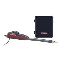
Covers motor type, speed, voltage, and electrical transformer, control station, and wiring.
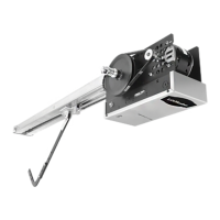
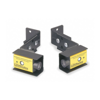
Details on drive, brake, bearings, and essential safety components like sensing devices.
Provides hanging weight and key physical dimensions of the operator.
Steps for assembling the operator track, including spacer brackets and idler assembly.
Instructions for mounting the operator unit to the frame.
Details on connecting the trolley carriage and drive chain, including tension adjustment.
Guidance on locating and mounting the header bracket above the door.
Steps for positioning and securing the operator unit horizontally.
Illustrates typical methods for supporting the operator from the ceiling.
Instructions for connecting the straight and curved door arms to the operator and door.
Details on compatible sensing edges and their connection methods.
Procedure for setting the open and close limit nuts for proper door travel.
Ensuring correct power supply and connecting wires according to the diagram.
Information on conduit knockouts for power and control wiring.
Guidance on standard C2/B2 wiring and special control wiring configurations.
Instructions for locating and mounting the control station near the door.
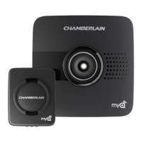
Connecting radio controls, interlock switches, and other access control equipment.
Steps for adjusting the friction clutch for proper operation and safety.
Instructions for releasing and re-engaging the door arm from the trolley.
Guidance on testing controls and safety devices, and important operational notes.
Information on the solenoid brake adjustment and friction pad replacement.
Recommended maintenance intervals and instructions for ordering repair parts.
| Drive Type | Chain Drive |
|---|---|
| Horsepower | 1/2 HP |
| Max Door Weight | 500 lbs |
| Battery Backup | No |
| Drive System | Chain |
| Lift Capacity | 500 lbs |
| Type | Garage Door Opener |
| Max Door Height | 7 feet |
| Voltage | 120V |
| Remote Control | Yes |