Do you have a question about the Chamberlain Liftmaster MT5025 and is the answer not in the manual?
Details on the motor type, horsepower, speed, voltage, and current ratings.
Information on transformer, control station, and wiring types.
Covers drive reduction, output shaft speed, door speed, and bearings.
Details on safety disconnect, sensing devices, and recommended safety measures.
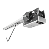
Provides hanging weight and key physical dimensions of the operator.
Instructions for assembling the operator track and installing spacer brackets.
Steps for positioning the track assembly onto the powerhead frame.
Guide for attaching the chain to the trolley carriage and setting chain tension.
Procedure for locating and mounting the header bracket above the door.
Steps for attaching the operator track to the header bracket and positioning unit.
Methods for supporting the operator from the ceiling or structure.
Instructions for connecting the door arm to the trolley and door bracket.
Guidance on installing and connecting sensing edges for safety.
Detailed steps for adjusting open and close limit nuts for proper door travel.
Ensuring correct power supply and making electrical connections safely.
Information on knockouts for routing power and control wiring.
Identifying the correct wiring configuration (C2 vs. B2) for operation.
Notes on non-standard wiring or optional accessory connections.
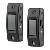
Recommendations for mounting the control station for optimal visibility and safety.
Connecting and using radio controls with the operator.
Connecting other access control devices like loop detectors.
Using an interlock switch to disable operation under certain conditions.
Procedure for adjusting the clutch for smooth operation and safety.
How to release the door arm from the trolley using the emergency disconnect.
Steps to re-engage the door arm with the trolley after manual release.
Verifying the proper operation of controls and safety devices after installation.
Information on the solenoid brake and its adjustment.
Recommended intervals for checking and servicing components like drive chain and bearings.
Contact information and required details for ordering replacement parts.
Kits for replacing the entire electrical box assembly.
Components for electrical box sub-assemblies like limit switches.
Kits available for replacing the operator motor.
Kits for clutch shaft and output shaft assemblies.
Kits containing hardware, track sections, and drive chains.
Kits for brake components, specifically for BMT models.
List of individual parts with part numbers and quantities.
Kits for variable components like transformers and capacitors.
Kit containing components for the limit switch assembly.
Kit containing components for the limit shaft assembly.
Comprehensive hardware kit for installation and assembly.
Parts related to the door track and drive chain.
Specific kits for electrical box replacements.
Kits for brake assemblies, detailing components and operator compatibility.
Kit containing parts for the clutch shaft assembly.
Kit containing parts for the output shaft assembly.
Detailed list of hardware components included in the kit.
Parts list for door track sections and drive chains.
Information on kits for replacing electrical boxes.
| Brand | Chamberlain |
|---|---|
| Model | Liftmaster MT5025 |
| Category | Door Opening System |
| Language | English |