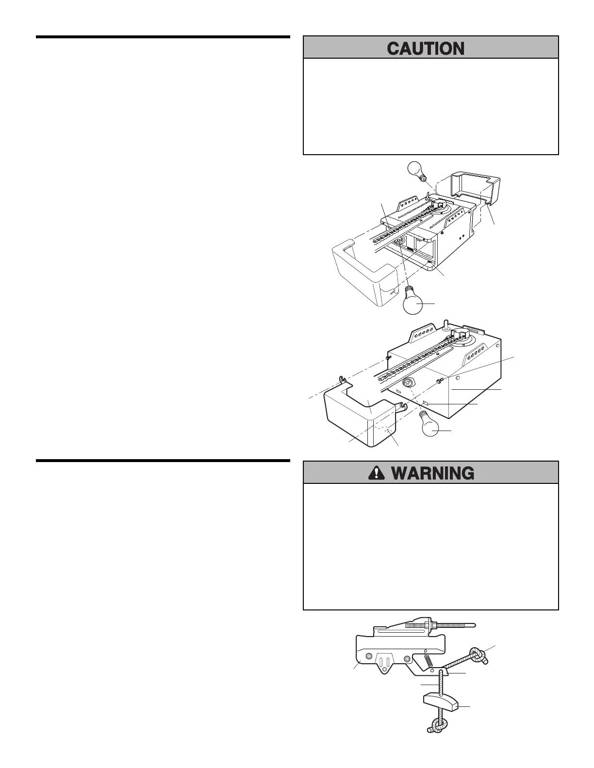
14
INSTALLATION STEP 8
Attach the Emergency Release Rope
and Handle
• Thread one end of the rope through the hole in the top
of the red handle so “NOTICE” reads right side up as
shown. Secure with an overhand knot at least 1"
(2.5 cm) from the end of the rope to prevent slipping.
• Thread the other end of the rope through the hole in the
release arm of the outer trolley.
• Adjust rope length so the handle is 6 feet (1.83 m)
above the floor. Ensure that the rope and handle clear
the tops of all vehicles to avoid entanglement. Secure
with an overhand knot.
NOTE: If it is necessary to cut the rope, heat seal the cut
end with a match or lighter to prevent unraveling.
Trolley
NOTICE
Overhand
Knot
Emergency
Release Handle
Rope
Trolley
Release Arm
To prevent possible OVERHEATING of the endpanel or light
socket,
• DO NOT use short neck or specialty light bulbs.
• DO NOT use halogen bulbs. Use ONLY incandescent.
To prevent damage to the opener:
• DO NOT use bulbs larger than 75W.
• ONLY use A19 size bulbs.
To prevent possible SERIOUS INJURY or DEATH from a falling
garage door:
• If possible, use emergency release handle to disengage
trolley ONLY when garage door is CLOSED. Weak or broken
springs or unbalanced door could result in an open door
falling rapidly and/or unexpectedly.
• NEVER use emergency release handle unless garage
doorway is clear of persons and obstructions.
• NEVER use handle to pull door open or closed. If rope knot
becomes untied, you could fall.
Lens
Guide
Lens
Tab
Lens
Slot
75 Watt (Max)
Light Bulb
INSTALLATION STEP 7
Install the Light(s) and Lens(es)
INSTALL THE LIGHTS
• Install up to a 75 watt maximum light bulb in each
socket. Light bulb size should be A19, standard neck
only. The light(s) will turn ON and remain lit for
approximately 4-1/2 minutes when power is connected.
Then the light(s) will turn OFF.
• Use A19, standard neck garage door opener bulbs for
replacement.
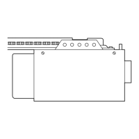
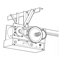
INSTALL THE LENSES: (Model M3100M) Figure 1
• Slide lenses into guides. Snap bottom tabs into lens
slots.
• Reverse the procedure to remove the lenses.
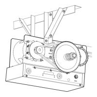
INSTALL THE LENS: (Model M350M) Figure 2
• Locate and loosen (approximately 1/8") the two screws
near top of motor unit front panel. Position lens against
panel with slotted tabs directly below screws. Slide lens
up to seat tabs behind screws. Snap bottom tabs of lens
into panel slots. Retighten top panel screws to secure
lens.
NOTE: Use only standard light bulbs. The use of short
neck or speciality light bulbs may overheat the endpanel or
light socket.
Lens Slot
75 Watt Max.
Light Bulb
Lens Tab
Light
Lens
Screw
Panel
Figure 1
Figure 2
 Loading...