EasyManua.ls Logo

Chamberlain MT5011U User Manual

Chamberlain MT5011U
28 pages
To Next Page IconTo Next Page
Page #1 background imageLoading...
Page #1 background image
Now with
Built in
Radio Receiver
315 MHz
Now with
Built in
Radio Receiver
315 MHz
MEDIUM DUTY DOOR OPERATOR
MODELS MT5011U & BMT5011U
INSTALLATION MANUAL
NOT FOR RESIDENTIAL USE
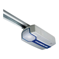
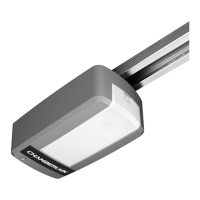
Your model may look different than the model illustrated in this manual.
THIS PRODUCT IS TO BE
INSTALLED AND SERVICED BY A
TRAINED DOOR SYSTEMS
TECHNICIAN ONLY.
Visit www.liftmaster.com to locate a
professional installing dealer in your area.
OPERATOR RATING: 12 cycles per hour,
50 cycles per day; maximum
Serial #
(located on electrical box cover)
Installation Date
2 YEAR WARRANTY
Questions and Answers:

Chamberlain MT5011U Specifications

General IconGeneral
TypeChain Drive
Max Lift Power1/2 HP
Horsepower1/2 HP
Voltage120V
Frequency60 Hz
CompatibilityStandard Garage Doors
Battery BackupNo
Safety FeaturesSafety sensors
Remote ControlYes
LightingYes
Remote Controls Included1
Security+ Rolling Code TechnologyYes
Wall Console IncludedYes
Works with MyQYes
Drive TypeChain
ConnectivityWi-Fi
SecuritySecurity+ Rolling Code Technology
WarrantyLimited lifetime warranty

Summary

Safety Information

General Safety Warnings

Discusses mechanical and electrical hazards requiring caution.

Cautionary Notes

Alerts to potential damage to the door or operator if cautionary statements are not followed.

Important Operational Notes

Emphasizes reading and understanding the manual before installation or maintenance.

Important Installation Instructions

Application and Features

Operator Specifications

Weights and Dimensions

Provides physical measurements and hanging weight of the operator unit.

Electrical and Motor Details

Outlines voltage, horsepower, current, and motor type specifications.

Mechanical and Safety Features

Covers door speed, output force, brake, duty cycle, and entrapment protection.

Environmental Operating Conditions

Specifies location requirements and operating temperature range.

Carton Inventory and Preparation

Carton Inventory Checklist

Lists components included in the operator package for installation.

Door Preparation Steps

Outlines necessary steps before installing the operator, like disabling locks.

Assembly: Track Components

Install Track Spacers

Attaching spacers evenly along the track length using pre-punched holes.

Install Front Idler Assembly

Securing the front idler component to the header end of the track.

Assemble Trolley and Take-Up Bolt

Assembling the trolley mechanism with its associated hardware for track movement.

Assembly: Track and Operator Connection

Slide Trolley onto Track

Moving the assembled trolley along the installed track.

Attach Track to Operator

Connecting the track assembly securely to the main operator unit.

Assembly: Chain Installation and Routing

Attach Chain to Trolley and Idler

Connecting the drive chain to the trolley and routing it around the front idler.

Route Chain Around Drive Sprocket

Wrapping the drive chain around the operator's drive sprocket.

Attach Chain to Trolley and Adjust Tension

Securing the chain to the trolley and adjusting for proper tension.

Typical Installation: Header Bracket

Mounting the Header Bracket

Instructions for securely fastening the header bracket to structural support.

Typical Installation: Operator Mounting

Securing the Operator Unit

Steps for temporarily supporting and then securely mounting the operator to the header bracket.

Typical Installation: Wiring Connections

Power and Ground Wiring Connections

Guidance on connecting power and ground wires to the operator's terminal strip.

Power Wiring Chart

A table detailing wire gauge requirements based on distance for power wiring.

Typical Installation: Control Station Wiring

Power and Ground Wiring Connections (Continued)

Continues guidance on power and ground wiring to the electrical box.

Installing the 3-Button Control Station

Steps for mounting and wiring the 3-button control station to the wall.

Typical Installation: Control Station and Antenna

Connecting Control Station Wires

Connecting wires from the control station to the operator's logic board.

Option A: Setup Radio Antenna

Instructions for locating and attaching the wire antenna to the electrical box.

Typical Installation: Radio Antenna

Option B: Antenna Attachment to Electrical Box

Alternative method for attaching the wire antenna to the electrical box.

Important Safety Instructions

Reiterates critical safety warnings for operation and maintenance of the operator.

Adjustment Procedures

Adjusting Travel Limits

Steps for setting the open and close travel limits for the door.

Adjusting the Clutch

Procedure for setting the clutch tension for smooth operation.

Entrapment Protection: LMEP Overview

LiftMaster Monitored Entrapment Protection (LMEP)

Explains the function and importance of LMEP devices for safety.

Entrapment Protection: Photoelectric Sensor Installation

Photoelectric Sensor Mounting Options

Details various methods for mounting sensors on walls or door tracks.

Entrapment Protection: Sensor Wiring and Mounting

Mounting the Photoelectric Sensors

Steps for centering and attaching sensors to brackets and running wires.

Primary Installation: CPS-U Photoelectric Sensors

Wiring diagram for primary installation of CPS-U photoelectric sensors.

Entrapment Protection: Alternate Wiring Options

Alternate Sensor Wiring Configurations

Shows wiring for 2-wire and 4-wire sensing edges and pneumatic sensors.

Logic Board Layout

Basic Programming: Wiring Type

Determine Operator Wiring Type

Explains how wiring type affects operator functionality and default settings.

Recommended B2 Wiring Configuration

Details the setup for B2 wiring with monitored entrapment protection.

Basic Programming: Alternate Wiring Types

Alternate C2 Wiring with Monitored Sensors

Describes C2 wiring functionality with monitored entrapment protection.

Alternate C2 Wiring without Monitored Sensors

Describes C2 wiring functionality without monitored entrapment protection.

Radio Control Modes and Operations

Basic Programming: Remote Controls

Single Button Remote Programming

Steps to program single-button remote controls to the operator.

Erasing All Programmed Remotes

Procedure to clear all previously programmed remote controls.

Wireless 3-Button Control Station Setup

Instructions for programming the 3-button control station wirelessly.

Timer-to-Close (TTC) Feature

Basic Programming: TTC and System Testing

Clearing the Timer-to-Close (TTC) Setting

How to disable or clear the TTC feature.

Timer Defeat Functionality

Explains how to temporarily disable the TTC feature using the stop button.

System Testing and Verification

Testing Control Station Operations

Verifies the function of OPEN, STOP, and CLOSE buttons.

Testing Limit Adjustments

Checks if the door opens and closes to the set limits correctly.

Testing Entrapment Protection Devices

Ensures safety devices correctly detect obstructions and reverse the door.

Testing Remote Control Operation

Verifies that remote controls can open and close the door.

Emergency Disconnect Procedures

Disconnecting Door from Operator

Steps to pull the emergency release handle to disengage the trolley.

Reconnecting Door to Operator

Steps to lift the arm and engage the roll pin to reconnect the door.

Troubleshooting Common Issues

Operator Not Responding to Commands

Addresses issues where the operator does not react to input signals.

Operator Noise Without Door Movement

Troubleshoots problems causing noise but no door motion.

Incorrect Door Movement Direction

Diagnoses issues causing the door to move in the wrong direction.

Door Drifting or Stopping Unexpectedly

Solves problems with the door drifting or stopping mid-travel.

Door Opens/Closes Too Far

Addresses issues where door limits are not set correctly.

Door Reverses Unexpectedly

Troubleshoots causes for the door reversing during its cycle.

TTC Not Functioning Correctly

Diagnoses problems with the Timer-to-Close feature.

Radio Functionality Issues

Covers problems with remote control response and learning.

Troubleshooting: Diagnostics and Special Modes

Diagnostic LED Table

Lists LED flash counts and their corresponding error statuses.

Restricted Close Mode Explanation

Wiring Diagram Overview

Available Accessories and Kits

315 MHz Remote Controls

Lists available remote controls for the operator.

Entrapment Protection Devices

Details various safety sensors and edge devices.

Antenna Options

Lists available antenna kits for extending radio range.

Control Stations

Describes different types of wired control stations.

Field Modification Kits

Lists kits for adding functionality like door-in-motion indicators.

Control Connection Diagrams

3-Button Control Station Wiring

Shows wiring for standard and multi-station 3-button setups.

2-Button Control Station Wiring

Illustrates wiring for 2-button control stations.

Device-to-Reverse Wiring Configurations

Diagrams for connecting sensing devices for door reversal.

External Interlock Wiring

Shows how to wire an external interlock device.

Related product manuals