11
POWER WIRING CHART
DISTANCE GAUGE
50 feet 14 AWG
100 feet 12 AWG
200 feet 8 AWG*
350 feet 6 AWG*
500 feet 4 AWG*
1000 feet 2 AWG*
Attach the door arms to the trolley and door bracket. Make
sure the open side of the notch on the door arm faces the
door.
Straight Door
Arm
Curved
Door Arm
Door Bracket
Lock Nut
Flange
Hex Nut
Vertical
Vertical
Door
Door Arm
Door
Bracket
Vertical
Center line
of Door
Use appropriate hardware to secure door bracket to door
(not provided). NOTE: When properly installed and adjusted the
door arm should be leaning back toward the operator slightly.
Refer to door manufacturer’s instructions for recommended
installation guidelines.
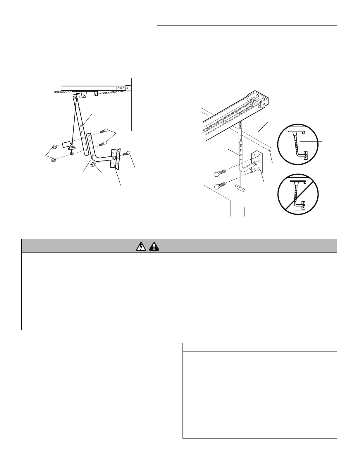
Bolt
3/8" - 16 x 3/4"
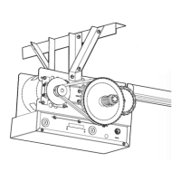
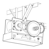
TYPICAL INSTALLATION
INSTALL THE OPERATOR
4
5
POWER AND GROUND WIRING CONNECTIONS
NOTE: Power and control wiring must be run in separate conduit
in accordance with national and local electrical codes. Must use 14
AWG or heavier wire for power wiring. Use conduit knockouts for
wiring as indicated on the electrical box labels.
IMPORTANT NOTE: Operator must be properly grounded. Failure
to properly ground the operator could result in electric shock and
serious injury.
DO NOT turn power on until you have fi nished making ALL power
and control wiring connections.
*
Maximum wire gauge that can be connected to the
operator’s terminal is 12 AWG. When a larger wire gauge is
required, the wire must be gauged down to 12 AWG.
USE COPPER WIRE ONLY.
Bolt
3/8" - 16 x 3/4"
To reduce the risk of SEVERE INJURY or DEATH:
• ANY maintenance to the operator or in the area near the
operator MUST NOT be performed until disconnecting the
electrical power and locking-out the power. Upon completion of
maintenance the area MUST be cleared and secured, at that time
the unit may be returned to service.
• Disconnect power at the fuse box BEFORE proceeding. Operator
MUST be properly grounded and connected in accordance with
national and local electrical codes. The operator should be on a
separate fused line of adequate capacity.
• ALL electrical connections MUST be made by a qualifi ed
individual.
• DO NOT install ANY wiring or attempt to run the operator
without consulting the wiring diagram.
• ALL power wiring should be on a dedicated circuit and well
protected. The location of the power disconnect should be
visible and clearly labeled.
• ALL power and control wiring MUST be run in separate conduit.
WARNING