26
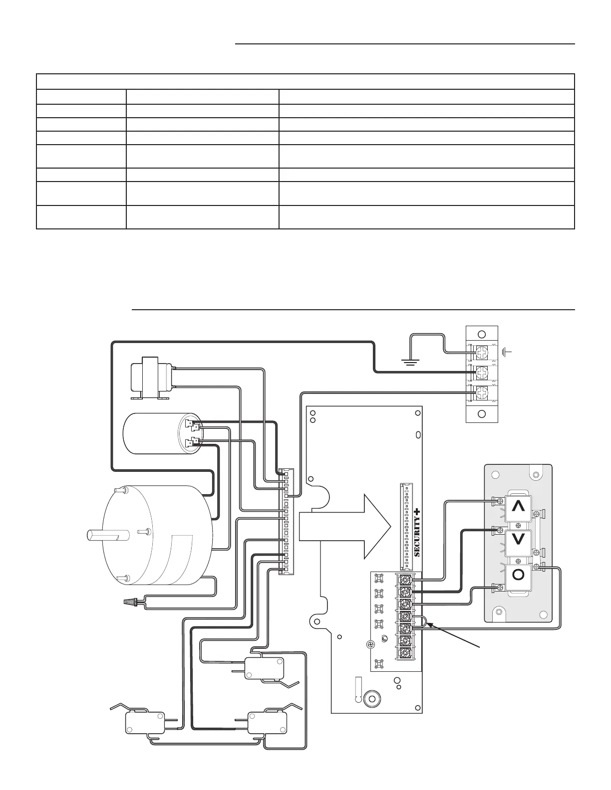
DIAGRAM
The status of the operator can be determined by counting the number of fl ashes of the LED on the logic board.
ANT
J2
AUX ANT
COM INTRLK STOP
LED
OPENCLOSE
TTC
LEARN
1
LMEP1 LMEP2
2345 67
STOP CLOSE OPEN
OPEN
CLOSE
STOP
Brake (BMT only)
Capacitor
Motor
Safety Limit
Switch
Open Limit
Switch
Close Limit
Switch
Yellow
Red
Grey
Purple
Orange
Grey
Yellow
Brown**
Brown**
Black
Black
Green
L2
L1
Red
Yellow
Blue*
White*
* If brake is not supplied, wires
are capped separately
** If interlock is not used,
wires are capped together.
Remove Jumper to install
external door interlock.
TROUBLESHOOTING
DIAGNOSTIC LED TABLE
# OF LED FLASHES STATUS FIX
1 System OK. Operating in C2 mode None
2 System OK. Operating in B2 mode None
3 Stuck CLOSE button Check for stuck close button or shorted close wire
4 Monitored Entrapment Protection Device
failure
Check for: 1) Misaligned or blocked Photoelectric Sensors.
2) Issue with Monitored Sensing Edge and/or wiring.
5 Incorrect motor direction Reverse the yellow and red motor wires on the capacitor.
6 Maximum run timer has timed out
(Maximum run time = 90 seconds)
Check clutch adjustment. Door height or speed may exceed the range the
operator can travel. Call Technical Support for assistance.
7 Logic Board Failure Replace Logic Board. NOTE: It is normal for the logic board LED to fl ash 4 times
when power is applied or cycled to the operator. (Not a logic board failure.)
RESTRICTED CLOSE
This method will allow you to close the door when LMEP device(s) are no longer working. Press and hold the CLOSE button until the
door reaches the closed limit. If the CLOSE button is released before the door reaches the closed limit the operator will stop and the
procedure will need to be repeated to fully close the door.