13
26
R
ing
Fastener
D
oor
Bracket
Straight
Door Arm
Curved Door Arm
T
rolley
4
5
D
o
o
r
B
r
a
c
k
e
t
3
C
u
t
t
h
i
s
e
n
d
Emergency
R
elease
Handle
4
5
3
Clevis Pin
6
P
ulley
2
0
0
m
m
(
8
”
)
m
i
n
.
Figure 1
Figure 2
Figure 3
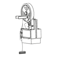
HARDWARE PROVIDED
7
5 4 7
3
6
Trolley
Pulley
2
0
0
m
m
(
8
”
)
m
i
n
.
Trolley
Pulley
2
0
0
m
m
(
8
”
)
m
i
n
.
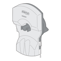
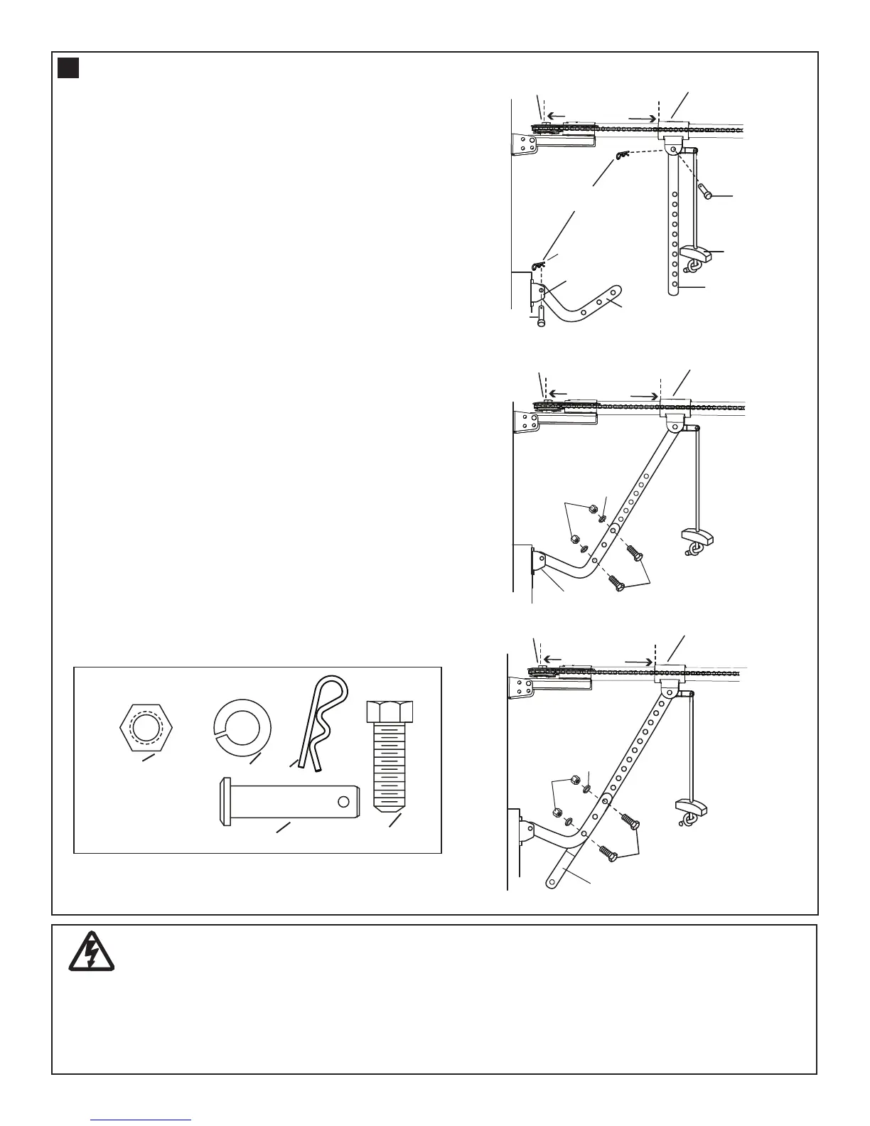
CONNECT DOOR ARM FOR
(SECTIONAL DOORS)
Make sure garage door is fully closed. Pull the emer-
gency release handle to disengage the trolley. Slide
the trolley assembly back 200mm from the idler pul-
l
ey.
Figure 1.
• Fasten straight door arm section to trolley
assembly using the hardware provided with
your opener.
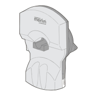
Figure 2.
• Bring arm section together. Find two pairs
of holes that line up and join sections.
Select holes as far apart as possible to
increase door arm rigidity.
Figure 3.
• If holes in curved arm are above holes in
the straight arm, disconnect straight arm
and cut approximately 150mm from
solid end. Re-connect to trolley with cut
end down as illustrated.
• Bring arm sections together.
• Find two pairs of holes that line up and join
with bolts, washers and nuts.
CONNECT ELECTRIC POWER
TO AVOID INSTALLATION DIFFICULTIES, DO NOT RUN THE GARAGE DOOR OPENER UNTIL
INSTRUCTED TO DO SO.
Connect the opener to a properly EARTHED power outlet, installed in compliance with local building
and electrical standards.
22
 Loading...