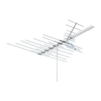
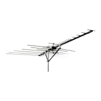
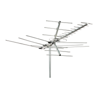
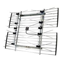
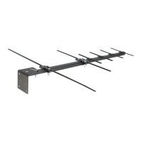
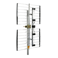
ULTRA-HI CROSSFIRE
®
UHF/VHF-FM ANTENNAS
WARNING: Installation of this product near power lines is DANGEROUS. For your safety, read
the enclosed “DANGER” booklet before beginning your installation.
READ CAREFULLY BEFORE INSTALLING
ANTENNA
1. If the antenna has a 2-piece crossarm, assemble the
two sections with screws and wing nuts as shown in
Figure 1. After assembling section, swing connecting
rods into position over terminals and fasten with
wing nuts. See Figure 2.
2. Open all elements on the antenna. NOTE: The ele-
ments on this antenna are tightly riveted. To avoid
bending them while opening, grip elements close
to pivot rivets as indicated in Figures 4 and 5.
Elements on corner reflector must be opened
before opening reflector crossarms. On main
crossarm, open elements “A” before element “B”
to avoid entrapment of elements “A”. See Figure 4.
3. Models 3671 and 3678 require installation of (2)
harnesses and (1) spacer at point of crossarm
assembly. Insert harnesses through spacer as
shown in Fig. 3 and Fig. 3A. Place on rivstuds and
fasten with (4) wing nuts. See Fig. 3B.
4. Thread standout into hole provided in lower reflector
crossarm. See Figure 6. Slit transmission line back
about 2¹⁄₂”. Strip ³⁄₄” of insulation from end of wire
and form eye. Attach terminals to formed ends and
crimp as shown. See Figure 7. (For best reception,
use twin lead UHF transmission line.) Attach trans-
mission line to tap-off terminals (see Figure 8) and
insert transmission line into standout grommet.
Crimp standout to secure transmission line.
5. Fasten antenna to mast as shown in Figure 9.
6. Adjust antenna towards transmitting stations, and
secure transmission line to mast using standouts
mounted below antenna.
3671 Printed in U.S.A. 2/01 Rev. E
P/N 51001
INSTRUCTION SHEET
Towards
Transmitting
Station
NOTE: THIS INSTRUCTION SHEET
COVERS ALL ANTENNAS OF
THIS SERIES
©2001 Channel Master LLC