EasyManuals Logo

Channel Plus MDS-6A User Manual

Channel Plus MDS-6A
16 pages
To Next Page IconTo Next Page
To Previous Page IconTo Previous Page
Page #10 background imageLoading...
Page #10 background image
MDS-6A
INSTALLATION MANUAL
Page 10 © Channel Plus, Inc. 2004 • All rights reserved. 4/04
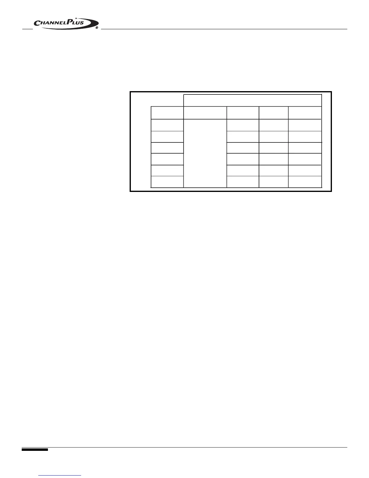
MCS Controller DIP Switch Configuration
When connecting MCS Controllers to the MDS-6A, all dip switches on all MCS
Controllers should be configured to reflect their correct Zone ID.
NOTE: If more than one MCS Controller is to be installed in a single zone, all wiring
should be paralleled (as illustrated in Figure 6C on the previous page) and both MCS
Controllers should be assigned the same Zone ID.
2.2 - WIRING
MCS CONTROLLERS -
CONT.
MDS-6A ZONE
12
DIP SWITCH #
1
2
3
4
5
6
X
X
X
X
X
X
ON ON
ON
OFF
OFF
OFF
OFF
OFF
OFF
OFF
ON
ON
ON
ON
ON
ON
ON
ON
#1 ON=Back
Light OFF
#1 OFF=Back
Light ON
3
4
Figure 7

Questions and Answers:

Question and Answer IconNeed help?

Do you have a question about the Channel Plus MDS-6A and is the answer not in the manual?

Channel Plus MDS-6A Specifications

General IconGeneral
BrandChannel Plus
ModelMDS-6A
CategoryController
LanguageEnglish