CHAPIN INTERNATIONAL, INC. P.O. BOX 549 700 ELLICOTT ST. BATAVIA, NY 14021-0549 www.chapinmfg.com 800-950-4458
— ASSEMBLY INSTRUCTIONS — CALIBRATION
— OPERATION
Tools required:
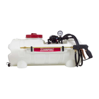
The pumping system draws solution from the tank,
through the strainer and to the pump. The pump forces
the solution under pressure to the nozzle.
The nozzle will spray a 72 inch wide swath. Check the
nozzle spray pattern by spraying water on a concrete
surface.
Regularly inspect the suction supply screen on the inside of
the tank. Flush with water to clear any accumulated debris.
Chemical labels may show application rates in gallons
per acre, gallons per 1000 square feet or gallons per 100
square feet. You will note that the tip chart shows all three
of these rating systems.
Once you know how much you are going to spray then
determine (from the tip chart) the spraying pressure (PSI),
and the spraying speed (MPH).
Conditions of weather and terrain must be considered
when setting the sprayer. Do not spray on windy days.
Protective clothing must be worn in some cases. Be sure
to read the chemical label carefully.
Determining the proper speed of the tractor can be done
by marking off 100, 200 and 300 feet. The speed chart
indicates the number of seconds it takes to travel the
distances.Set the throttle and with a running start travel the
distances.Adjust the throttle until you travel the distances
in the number of seconds indicated by the speed chart.
Once you have reached the throttle setting needed,
mark the throttle location so you can stop and go again
(returning to the same speed).
Add water and proper amount of chemical to tank and
drive to the starting place for spraying, with the mixing
valve open and nozzle valve closed.
When you are ready to spray, turn the nozzle valve to the
“on” position and turn the mixing valve to the off position.
This will start solution spraying from the tip once the unit is
motion.
— AFTER SPRAYING
After use, ll the sprayer part way with water. Tow the
sprayer and allow clear water to be pumped through the
plumbing system and out through the spray nozzle.
Remove nozzle from the nozzle. Wash tips thoroughly with
water or cleaning solution (appropriate for chemical used).
Blow out orice, clean and dry. If orice remains clogged
clean it with a ne bristle (not wire) brush, or with a tooth
pick. Do not damage the orice. Water rinse and dry tips
before storing.
Store sprayer tank upside down, in a warm dry location.
When you are ready to spray, turn the nozzle valve to the
“on” position and turn the mixing valve to the off position.
This will start solution spraying from the tip once the unit is
motion.
— WINTER STORAGE
Drain all water and chemical out of sprayer, paying special
attention to hoses, tubes and valves. These items are
especially prone to damage from chemicals and freezing
weather.
The sprayer should be winterized before storage by
removing the pump tubes and and draining all hoses
completely
— TIP CHART
— SPEED CHART
Tip No.
Spray
Height
GALLONS PER MINUTE – BASED ON WATER
2 MPH 2.5 MPH 3 MPH
3.5
MPH
4
MPH
FT 3 18” 0.23 0.25 0.26 0.27 0.28
FT 4 18” 0.3 0.32 0.34 0.35 0.36
FT 5 18” 0.36 0.37 0.38 0.41 0.43
FT 7.5 18” 0.5 0.52 0.57 0.64 0.67
FT 10 18” 0.55 06 0.73 0.77 0.81
Tip
No.
Spray
Height
GALLONS PER ACRE – BASED ON WATER
2 MPH
2.5
MPH
3 MPH
3.5
MPH
4 MPH
FT 3 18” 9.5 8.3 7.2 6.4 5.8
FT 4 18” 12.4 10.6 9.4 8.3 7.4
FT 5 18” 14.8 12.2 10.5 9.7 8.9
FT 7.5 18” 20.6 17.2 15.7 15.1 13.8
FT 10 18” 22.7 19.8 20.1 18.2 16.7
Speed in MPH
(Miles Per Hour)
Time Required in Seconds to Travel a distance of:
100 . 200 . 300 .
1.0 68.0 136 205
2.0 34.0 68 102
3.0 23.0 45 68
4.0 17.0 34 51
5.0 14.0 27 41
6.0 11.0 23 34
7.0 9.7 19 29
8.0 8.5 17 26
9.0 7.6 15 23
10.0 6.8 14 20