27
If the electronic circuit board is replaced, make sure that the parameters set are those specific to the
boiler model, as indicated in the documentation available from the authorised Service Centre.
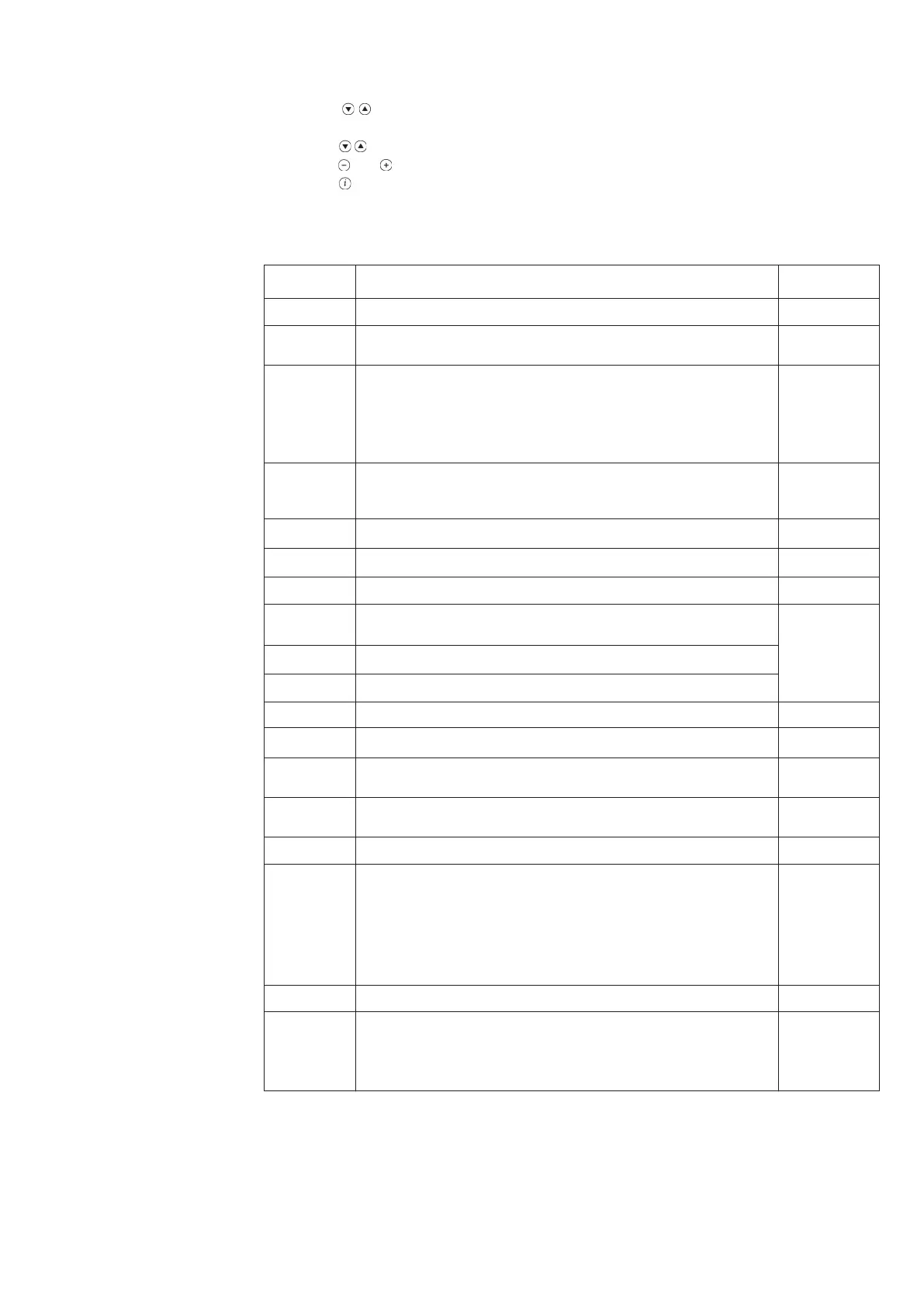
Table 4
Parameter N.
H90
H91
H505
H507
H516
H532
H533
H536
H612
H613
H544
H545
H552
H553
H615
H632
H641
H657
Description
Setting for domestic hot water reduced temperature (°C)
D.H.W. (Domestic Hot Water) program
(0 = enabled; 1 = disabled)
Maximum temperature (°C) of the central heating circuit HC1 corresponding to:
- the main circuit in systems with just one zone;
- the circuit of the zone where the QAA73 temperature control device is installed
in case of systems with more than one high-temperature zone;
- the high temperature zone circuit in mixed systems and if the SIEMENS AGU2.500
accessory is used.
Maximum temperature (°C) of the central heating circuit HC2 of a system with
more than one zone, corresponding to the circuit of the low-temperature zone if the
SIEMENS AGU2.500 accessory is used.
Automatic Summer / Winter switching temperature (°C).
Selection of temperature curve of central heating circuit HC1 (see Graph 1)
Selection of temperature curve of central heating circuit HC2 (see Graph 1)
Maximum speed at maximum output in heating mode
(rpm - maximum speed limitation)
Setting value of required speed (rpm) at low-fire
Setting value of required speed (rpm) at high-fire
Pump post-circulation time in central heating mode (min)
Burner operating pause time between two start-ups (s)
Hydraulic system setting (see instructions provided with the SIEMENS AGU2.500
accessory). H552 = 50 with AGU2.500
Configuration of heating circuits
H553 = 12 with AGU2.500
Programmable function
Configuration of system with low loss header P1
H632 = 00001111 with AGU2.500
The value of Bit could be 1 or 0.
Press the keys 5 and 6 to select the bit to modify (b0 is the bit on the right, b7 is the
last bit on the left).
To modify the Bit value press on the keys 7 and 8
Fan post-purge interval (s)
Setpoint of autonomous ANTILEGIONELLA function
60...80 °C = setting temperature range
0 = function inactive
The boiler parameters may only be modified by professionally qualified staff proceeding as fol-
lows:
a) press the , keys on the boiler’s front panel together for about 3 s until the parameter H90
appears on the display;
b) press the keys to select the parameter for modification;
c) press the and keys to modify the parameter;
d) press the key to exit the programming function.
The following are the parameters generally used:
15. Setting the boiler
parameters
Factory setting
10
1
80
80
20
15
15
Refer to
paragraph
12.1
10
180
2
21
9
00001100
10
0