16
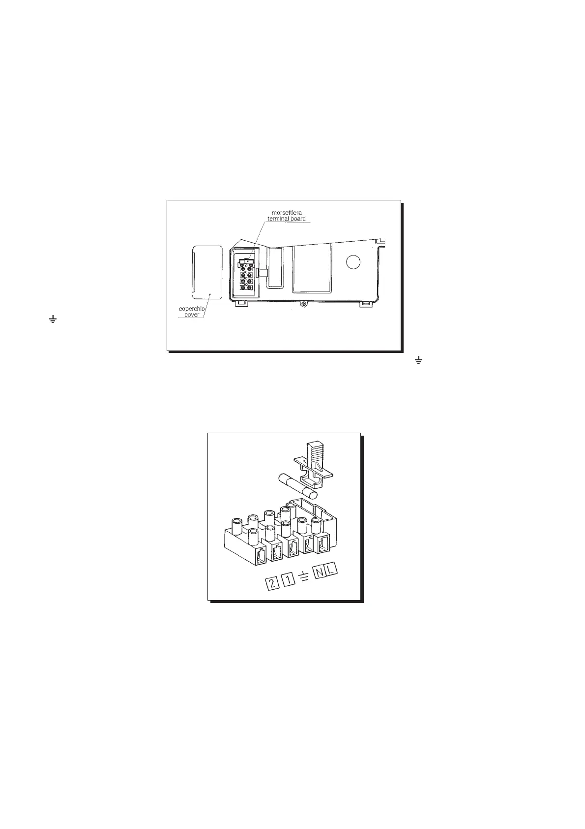
Figura 11
εικνα 11
9402250715
Σύνδεση παροχής ρεύµατος
Η ασφάλεια τησ συσκευήσ εγγυάται µνο αν έχει γίνει σωστή γείωση
µε βάση τισ διεθνείσ συµβάσεισ και συµφωνίεσ.
Συνδέστε το λέβητα σε µονοφασικ ρεύµα 220-230V και γειώστε την
παροχή του ρεύµατοσ µε τη βοήθεια του καλωδίου που παρέχεται.
Βεβαιωθείτε τι έχουν συνδεθεί σωστά οι πολικτητεσ.
Χρησιµοποιήστε διπολικ διακπτη µε διάκενο τουλάχιστο 3mm
ανάµεσα στουσ πλουσ.
Σε περίπτωση που αντικαταστήσετε το καλώδιο, τοποθετήστε ένα
HAR HOS VV-F’ 3x0,75 mm
2
µε µέγιστη διάµετρο 8mm.
...πρσβαση στον πίνακα ηλεκτρικήσ παροχήσ.
- Κψτε την ηλεκτρική παροχή
µε τη βοήθεια του διπολικού
διακπτη.
- Ξεβιδώστε τισ 2 βίδεσ που
συγκρατούν τον πίνακα στο
λέβητα.
- Περιστρέψτε τον πίνακα.
- Ξεβιδώστε το καπάκι και
αποκτήστε πρσβαση στισ
καλωδιώσεισ (εικνα 10).
L: Καφέ φάση
N: Μπλε ουδέτεροσ
: Κίτρινο/πράσινο γείωση
(1), (2): Τερµατικ θερµοστάτη
δωµατίου
Figura 10
εικνα 10
Connecting the mains supply
Electrical safety of the appliance is only guaranteed by correct grounding,
in compliance with the applicable laws and regulations.
Connect the boiler to a 220-230V monophase + ground power supply by
means of the three-pin cable supplied with it and make sure you connect
polarities correctly.
Use a double-pole switch with a contact separation of at least 3mm in
both poles.
In case you replace the power supply cable fit a HAR H05 VV-F’
3x0.75mm
2
cable with an 8mm diameter max.
…access to the power supply terminal block
• isolate the electrical supply to the
boiler by the double-pole switch;
• unscrew the two screws securing the
control board to the boiler;
• rotate the control board;
•
unscrew the lid and gain access to the
wiring (Figure 10).
A 2A fast-blowing fuse is incorporated
in the power supply terminal block (to
check or replace the fuse, pull out the
black fuse carrier).
(L) = Live brown
(N) = Neutral blue
( )=Ground yellow/green
(1) (2) = room thermostat
terminal
0004190400
Fitting a room thermostat
• gain access to the power supply terminal block
(Figure 11) as described in the previous section;
• remove the jumper placed on terminals (1) and
(2);
• insert the duplex cable through the core hitch and
connect it to the two terminals.
Σύνδεση θερµοστάτη χώρου
- Αποκτήστε πρσβαση στον πίνακα
ηλεκτρικήσ παροχήσ (εικνα 11) πωσ
περιγράφεται στην προηγούµενη
εντητα.
- Αφαιρέστε τη γέφυρα ανάµεσα στα
τερµατικά (1) και (2).
-Τοποθετήστε ένα διπλ καλώδιο και
συνδέστε το στα δύο τερµατικά.
Σύνδεση χρονοδιακπτη
(Κεντρική Θέρµανση)
- Ξεβιδώστε τισ δύο βίδεσ που προστατεύουν τον πίνακα ελέγχου
του λέβητα και στρέψτε τον προσ τα κάτω.
- Ξεβιδώστε τισ δύο βίδεσ του καλύµµατοσ τησ πλακέτασ και
αφαιρέστε το ώστε να εµφανιστεί η πλακέτα.
- Συνδέστε το µοτέρ του χρονοδιακπτη στη διάταξη Α3 τησ
πλακέτασ (επαφέσ 1 και 3).
- Συνδέστε τισ επαφέσ του χρονοδιακπτη στη διάταξη Α3 τησ
πλακέτασ (επαφέσ 2 και 4) αφού αφαιρέσετε τη γέφυρα
βραχυκύκλωσησ.
Εάν εγκαταστήσετε χρονοδιακπτη µπαταρίασ, αφήστε ελεύθερεσ
τισ επαφέσ 1 και 3 τησ διάταξησ Α3.
Connecting
a programming clock
*
remove the two screws securing the control board to the boiler and
hinge it downward;
*remove the 2 screws fixing the control board cover and hinge it upward;
* connect the programming clock motor to the main PCB A3 connector
(terminals 1 and 3);
* connect the programming clock switch to the A3 connector terminals
(2 and 4) and remove the jumper.
In case you are fitting a battery-operated programming clock do not
connect the A3 connector terminals (1 and 3).
καπάκι
βάση ακροδεκτών