18
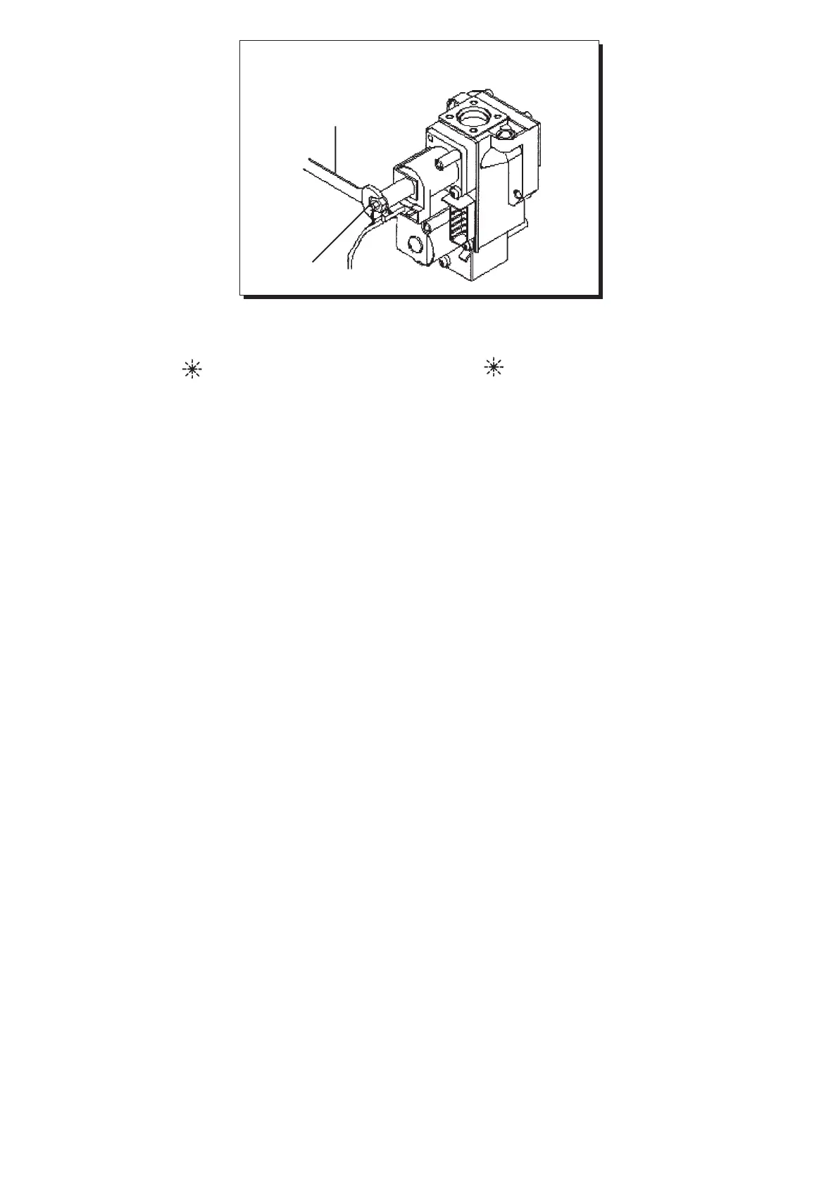
∆1) Ρύθµιση για την ονοµαστική ισχύ (A εικνα 13).
- Ανοίξτε τη βάνα αερίου και περιστρέψτε το κοµβίο (1) στη θέση
λειτουργίασ χειµώνα (
).
- Ανοίξτε το ζεστ νερ µιασ βρύσησ για να πιάσετε την ελάχιστη
παροχή 10 λίτρα/λεπτ ή βεβαιωθείτε τι έχουν ρυθµιστεί οι
µέγιστεσ απαιτήσεισ για ζεστ νερ.
- Αφαιρέστε το κάλυµµα του ρυθµιστή.
- Ρυθµίστε την µπρούτζινη βίδα για να πάρετε την πίεση που
αναγράφεται στον πίνακα 1 στη σελίδα 19.
- Ελέγξτε τι η δυναµική πίεση παροχήσ του λέβητα, πωσ µετράται
στο σηµείο εισδου (Pb) τησ βαλβίδασ πίεσησ (εικνα 12) είναι
σωστή (30mbar για G30, 37mbar για G31, 20mbar για φυσικ αέριο).
∆ 2) Ρύθµιση για µειωµένη αποδιδµενη ισχύ (B εικνα 13).
- Αποσυνδέστε το καλώδιο παροχήσ του ρυθµιστή και ξεβιδώστε
την κκκινη βίδα για να πιάσετε την πίεση που αντιστοιχεί στη
µειωµένη αποδιδµενη ισχύ (πίνακασ 1).
- Συνδέστε το καλώδιο.
-Τοποθετήστε το καπάκι του ρυθµιστή και ασφαλίστε τη βίδα.
∆3) Τελικς έλεγχος.
-Τοποθετήστε την επιπλέον ετικέτα, αναφέροντασ τον τύπο αερίου
και τισ ρυθµίσεισ που έγιναν.
C1) Adjustment to rated output:
• open the gas tap and rotate knob (1) to set the boiler to the Winter
setting (
);
• open a hot water tap to reach a minimum 10 l/minute flow rate or
ensure that maximum heating requirements are set;
•remove the modulator cover;
• adjust the tube brass screw (A Fig. 13) to obtain the pressure settings
shown at table 1 on page 19;
• check that boiler feeding dynamic pressure, as measured at the inlet
gas valve pressure test point (Pa) (Figure 12) is correct (30 mbar for
G.30, 37 mbar for G.31, 20 mbar for natural gas);
C2) Adjustment to reduced heat output:
• detach the modulator feeding cable and unscrew the screw (B Fig. 13)
to reach the pressure setting corresponding to reduced heat output
(see table 1 on page 19);
• connect the cable again;
• fit the modulator cover and seal the fixing screw.
C3) Final checks
• apply the additional dataplate, specifying the type of gas and settings
applied;
b
a
Figura 13
εικνα 13
0211_1507
valvola Honeywell