14Ref. : CH - 1249 - A - 2
Operation
Lower mask (56)
Front sides (57 - 58)
Side restraint (59)
Middle sides (62)
Rear sides (60 - 61)
Upper rear (63)
Upper heat-insulator (33)
Front top (65)
Middle top (67)
Rear top (66)
Control panel
Lower left and right façades
(69 - 70)
Upper façade (68)
(see figure 14)
Method
• Place the lower mask on both lower feet at the front of the boiler (this part is pre-cut
to allow passing of sludge tubing, or can also be taken out)).
• Hook the front sides onto the side-rails and fasten them using the axis screws (Ø 8)
in the upper part and at the bottom using a TH M 5 screw on the lower foot.
• Extract the restraint from the side panel by tilting it, insert it in the side heat-insulator’s
slit, and hook it on the assembly linkage; Tighten the axis screw.
• (only for boilers with 7, 8 or 9 sections)
• Put the middle side on the side-rails. Slide it so that the axis of the restraint enters the
orifice provided.
• Extract the side restraint in the same way as for the front side.
• Put the rear side on the side-rails, and slide so that the side’s return fold casings the
lower rear (51) “s fold and the axis of the restraint enters the orifice provided.
• Secure the rear sides on the lower rear using 4 HM 5 x 10 screws.
• Pin the upper rear on the sides and click it in downwards in the keyhole slots provided
for this purpose.
• Place the upper heat-insulator on the side-rails (slit at the front).
• Place the front top on the side axes and push it forwards to bumper.
• (only for boilers with 7, 8 or 9 sections)
• Place it on its axes and push it forwards until it joins up with the front top.
• Place it on its axes and push forwards until it joins up with the front or middle side in
the case of a boiler 7, 8 or 9 sections.
• Secure it on the upper rear (2 HM x 10 screws).
• Assemble the control board as indicated on this page.
• Click the faþades in laterally and downwards on the buttons fastened on the sides’
folds.
Locking is done by the central feet.
• Engage both axes in the lower faþades’ holes.
• Press the façade on the sides.
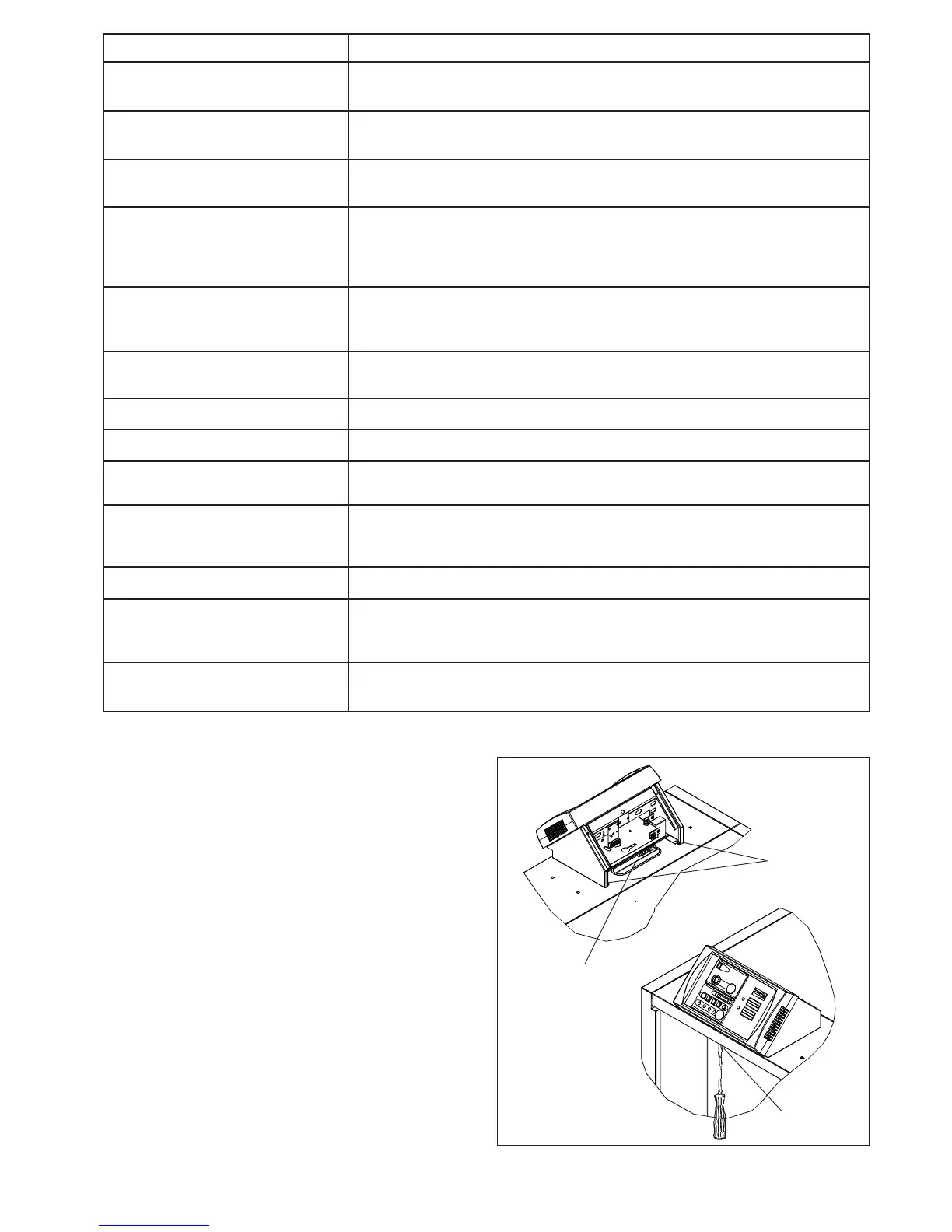
- fit the control panel on the front top while routing the
probe cables through the opening included to this
effect
- engage the pins under the panel into the slots, and
pull the control panel towards you.
- Lock it using the 2 plactic pins (A) and the M5 screw
(B) on the top front
CONTROL PANEL ASSEMBLY
N04214DSF
Fig. 16
plastic pins
A
Probe cables
B