4Ref. : CH - 1249 - A - 2
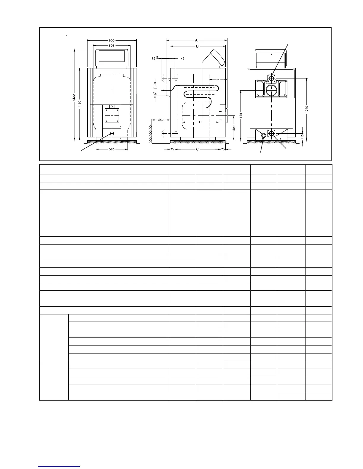
2 . 5 Technical data
Flow DN 65
Fig. 1
Return DN 65
Drain Rp 1 1/2" orifice
Rp 2" orifice for
sludge flushing
36
130-170
6
1335
1240
1090
292
935
180
170
270
160
6
15
30-90
110
0,11
0,40
140-185
0,5-0,8
201-265
232-306
161-180
92,7 - 93 6
139 - 183
0,5 - 1,0
199 - 262
229 - 303
147 - 166
93,4 - 94,2
39
250-290
9
1845
1750
1600
292
1445
200
260
390
232
6
50
30-90
110
0,07
0,25
271-317
1,5-2,3
388-454
448-524
170-188
92,4 - 93,2
270 - 315
1,7 - 2,5
385 - 451
445 - 520
156 - 174
93,0 - 93,8
37
170-210
7
1505
1410
1260
292
1105
180
200
320
184
6
21
30-90
110
0,09
0,33
184-229
0,7-1,2
263-328
303-378
164-182
92,6 - 93,4
182 - 227
0,8 - 1,3
261 - 325
301 - 375
150 - 168
93,2 - 94,1
38
210-250
8
1675
1580
1430
292
1275
200
230
350
208
6
31
30-90
110
0,08
0,28
228-273
1,3-1,8
325-391
375-451
167-185
92,5 - 93,3
226 - 271
1,5 - 2,0
323 - 388
372 - 447
153 - 171
93,1 - 93,9
35
90-130
5
1165
1070
920
292
765
180
140
230
136
6
9
30-90
110
0,13
0,52
97-142
0,2-0,5
139-202
160-234
158-177
92,8 - 93,7
96 - 140
0,2 - 0,5
137 - 200
158 - 231
144 - 163
93,5 - 94,4
Réf. chaudière : N°
Output : kW
Number sections
Dimensions : Cote A : mm
Cote B : mm
Cote C : mm
Cote Y : mm
Combust. chamber depth P : mm
Smoke hood Ø D : mm
Chamber volume : l
Flue path volume incl-chamber : l
Water system vulume : l
Working pressure : bar
Waterside pressure loss at (∆t = 15 K ) : mbar
Thermostat range adjustement : °C
Limit stat max setting. (temperature) : °C
Standing losses (NFD 30 002) : %
Heating maintenance needs : %
Flame output (P nom) : kW
Chamber pressure : mbar
Massic-flow oil flues : Kg/h
Massic-flow gas flues : Kg/h
Flue gas temperature : °C
Combustion efficiency (2) : %
Flame output (P nom) : kW
Chamber pressure : mbar
Massic-flow oil flues : Kg/h
Massic-flow gas flues : Kg/h
Flue gas temperature : °C
Combustion efficiency (2) : %
34
70 - 90
4
995
900
750
292
595
180
110
190
112
6
5
30 - 90
110
0,14
0,74
75 - 98
0,1 - 0,2
108 - 140
124 - 161
155 - 174
93,0 - 93,9
74 - 97
0,1 - 0,3
106 - 138
123 - 160
141 - 160
93,6 - 94,5
* Dimensions with water
connection sleeve
(1) The maintenance coefficient is for an average boiler temperature of 70 °C .
(2) Values given for rated output, 20 °C room temperature, boiler temperature 80 °C, return 60 °C.
(3) CO
2
(indicative) - 13 % (oil) - 10 % (gas)
2 Savers(3)
4 Savers (3)
N04153.DSF