6Ref. : CH - 1249 - A - 2
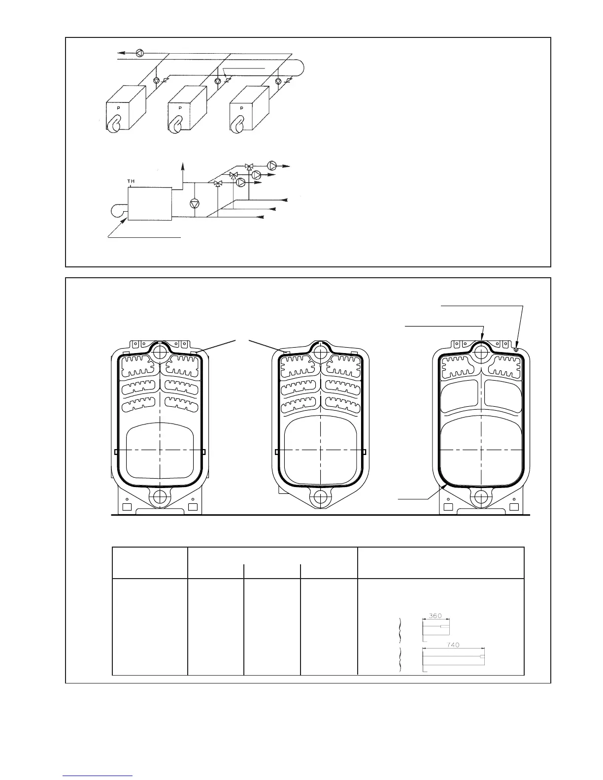
Boiler Number of sections
ref. Front Middle Rear
34 1 2 1 None
35 1 3 1 None
36 1 4 1 Short
37 1 5 1 Short
38 1 6 1 Long
39 1 7 1 Long
Distributors
Cord
S
S
E
Fig. 5
Sludge flush
Non return valve
Fig. 4
DIAGRAM OF THE ELEMENTS
S : tightening markings
E : spacing pads
S
Front Middle Rear
Assembly marking
Cord junction point
SSS
Minimum flow rate must be provided at all times,
whatever the rate of operation, either :
- by means of the main flow pump, provided that the
system has no mixing valve between each boiler and
the pump, and that the pump operates continuously,
- by means of a recycling pump or a loading pump
operating permanently.
In the case of a recycling pump or a loading pump per
boiler, and to avoid parasitic flows in the other boilers,
position non return valves upstream from the return
connection.
The burner must be controlled by the recycling or
loading pump. It can only be put in operation if the pump
operates. Secondarily, a flow control device, combined
with the TH thermostat, can be mounted on the return
of the boiler, downstream from the recycling or loading
pump.
To vents
00306N0225200.PLT
N0226701.PLT