InstallationmanualChargestormConnected page4
ChargestormAB
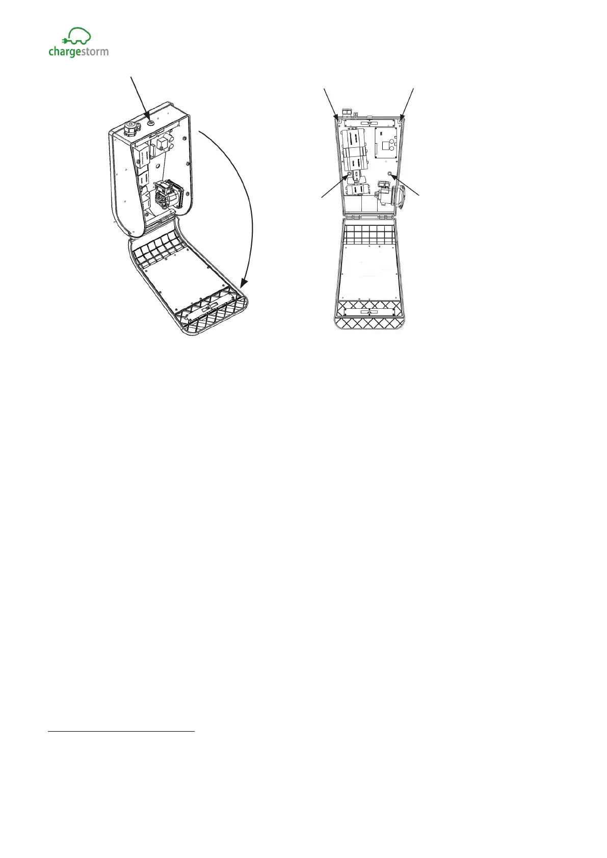
Figure 6 Open front cover with the key and fasten the unit on the wall
Step 5) Connect incoming power
2
-Pull the power cable through the cable gland about 450 mm. Peal
the wires about 8mm at the end. The wires cross section area must not exceed 16mm
2
. Make sure
protected ground wire is longer than the other wires sot that it will be the last wire to detach if pulled.
Connect the supply wires to the terminal blocks. Check that L1-L3, PE and N is correctly mated
between female and male connector. Put back protection cover and close and lock with the key.
2
For three-phase Chargestorm Connected models with dual connectors is incoming power connected to
the DIN rail mounted terminal blocks at the bottom between the connectors. Check that L1-L3, PE and
N is correctly mated. For schematics see chapter 11.
GACELL A/S - Sletten 17 - DK 7500 Holstebro - 961 02 961



 To Next Page