27
Dangerous voltage generated
!
See the user’s manual
> 25 V Voltage > 25 V
W
0
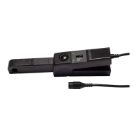
Compensated leads
Buzzer active
P
Constant operation (no automatic shutdown)
Batteries flat
W
0
Fixed and Flashing :
incorrect compensation of the leads
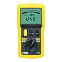
2.2.2. Bargraph
Insulation > 2 GΩ
Insulation < 50 kΩ
2.2.3. Digital display
BAT Batteries low – must be changed
OL Range exceeded
- - - Insulation < 50 kΩ at 250 V, < 100 kΩ at 500 V
or < 200 kΩ at 1000 V
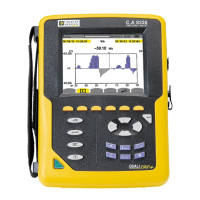
2.3. Control keyboard
2.3.1. Yellow key
When this yellow key is pressed, a high voltage is generated for
insulation testing. However, if a voltage greater than 25 V has
been detected, no insulation testing is allowed and the key
becomes inactive.
In all cases, this key is only active for as long as it is pressed,
except in the TIMER mode specific to the C.A 6525 (first press
= activation, second press = deactivation).
2.3.2. ALARM key (C.A 6523 and C.A 6525)
The ALARM key can be used to activate/deactivate the alarm
thresholds during insulation, resistance and continuity
measurements.
When associated with the and keys, it can be used to
program the values of these thresholds.
2.3.3. Key (C.A 6523 and C.A 6525)
When programming the alarm thresholds, the key makes
the following elements flash in succession :
■ the measurement unit digit (if there is one),
■ the thousands digit,
■ the hundreds digit,
■ the tens digit,
■ the units digit,
■ the decimal separators,
■ the type of threshold (upper or lower),
■ and it then returns to the measurement units.
 Loading...