29
3.1.2. Insulation measurement
If there is not a dangerous voltage (see § 3.1.1.), the user can
then measure the insulation by pressing the yellow key. The
high voltage is then generated between the terminals (marked
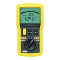
+ and -). The value of the measurement is shown on the
logarithmic scale of the bargraph and on the digital display, with
the corresponding MΩ or GΩ symbol. As soon as the yellow
key is released, the instrument returns to voltage measurement
mode.
If the voltage generated may be dangerous, the symbol
is displayed.
The instrument indicates if the value measured is outside
its measurement range. If the insulation resistance is greater
than 2 GΩ, the OL symbol is displayed on the digital
measurement display. When the measurement is greater than
2 GΩ, the symbol lights up on the right-hand side of the
bargraph.
Similarly, if the insulation resistance is less than 50 kΩ at 250 V,
100 kΩ at 500 V or 200 kΩ at 1000 V, the digital measurement
display indicates “ - - - “ . When the measurement is less than
50 kΩ, only the symbol lights up on the left-hand side of the
bargraph.
Specific remark concerning the C.A 6523 and C.A 6525 :
A programmed alarm threshold can activate itself (see § 4.5).
Specific remark concerning the C.A 6525 :
The measurement can be timed (see § 4.7).
3.2. Continuity
The continuity measurements correspond to the “ 20 Ω + “ or “
20 Ω - “ switch positions.
The instrument takes a measurement at I ≥ 200 mA and the "Ω"
symbol is displayed. If the threshold is active (ALARM function)
with the buzzer on, the buzzing starts very quickly (tens of
milliseconds); even before the measurement is displayed.
Between the “ 20
ΩΩ
ΩΩ
Ω + “ position and the “ 20
ΩΩ
ΩΩ
Ω - “ position,
the direction of the current is inverted. The result of the
measurement is the mean (to be calculated by the user) of the
value displayed in the “ 20 Ω + “position and the value displayed
in the “ 20 Ω - “ position.
Continuity measurements shall be performed on idle circuits.
The fuse protecting against external voltages is checked
when the apparatus is started up and at the end of each
continuity measurement.
The instrument indicates if the value measured is outside
its measurement range. If the resistance is greater than 20 Ω,
the OL symbol is displayed on the digital measurement display.
Specific remarks concerning the C.A 6523 and C.A 6525 :
The resistance of the measurement leads can be compensated
(see § 4.6).
A programmed threshold may trigger an alarm (see § 4.5).

 Loading...


