Do you have a question about the Chauvin Arnoux C.A 8336 and is the answer not in the manual?
Details the contents of the device package and accessories.
Outlines the primary roles and capabilities of the analyzer.
Lists the specific electrical parameters the device can measure.
Describes various display modes like waveforms, trends, and alarms.
Details user-configurable settings for the device.
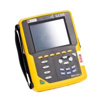
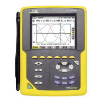
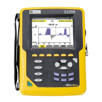
Provides a visual overview of the device's layout and controls.
Explains how to power the device on and off.
Describes the screen interface and information displayed.
Explains the function of each button on the keypad.
Details the various input and output ports on the device.
Information on battery and mains power operation.
Describes the retractable stand for device positioning.
Lists and defines common abbreviations used.
Step-by-step guide for powering on and initial setup.
How to access and navigate the configuration menu.
Instructions for connecting measurement leads.
Connection diagrams for single-phase systems.
Connection diagrams for split-phase systems.
Connection diagrams for three-phase systems.
Detailed steps for connecting the device.
Overview of key device functions.
Navigating the main configuration screen.
How to change the display language.
Setting the device's date and time.
Configuring screen settings like brightness and colors.
Selecting analysis parameters and methods.
Defining the electrical connection setup.
Configuring current and voltage sensor parameters.
Setting thresholds for transients and inrush currents.
Configuring data logging parameters.
Setting up and programming alarm conditions.
Options for deleting recorded data.
Displays device information like firmware and serial number.
Capturing and analyzing voltage/current transients.
Setting up transient capture parameters.
Viewing recorded transient events.
Capturing and analyzing motor start-up currents.
Configuring inrush current capture settings.
Viewing inrush current capture parameters.
Displaying RMS values during inrush.
Analysis of harmonics in phase-to-neutral voltage.
Analysis of harmonics in current signals.
Analysis of harmonics in apparent power.
Analysis of harmonics in phase-to-phase voltage.
Advanced harmonic analysis for neutral heating and machines.
Displays RMS values of voltage and current waveforms.
Displays THD values for voltage and current.
Displays peak factor for voltage and current signals.
Shows min/max/avg voltage and current values.
Displays multiple measurement types concurrently.
Vector representation of voltage and current fundamentals.
Setting up and configuring alarm parameters.
Defining start/stop times for alarm recording.
Viewing recorded alarm campaigns.
Listing detected alarms within a campaign.
Removing recorded alarm campaigns.
Deleting all stored alarm data.
Setting up and initiating data logging.
Modifying trend recording settings.
Accessing a list of saved recordings.
Removing recorded data files.
Displaying recorded data and their characteristics.
Details of a specific recorded data file.
Visualizing recorded data as curves over time.
Power measurements for 3-phase systems.
Displays active, reactive, and apparent power.
Shows PF, DPF, and phase shift.
Displays energy consumed by the load.
Displays energy generated by the load.
Power and energy for individual phases.
Total system power and energy calculations.
Initiating the energy measurement process.
Suspending or stopping energy measurement.
Resetting all energy metering values.
Capturing and saving current screen displays.
Managing saved screen captures.
Displaying previously saved screens.
Removing saved screen captures.
Specifies operating and storage temperature/humidity.
Details device dimensions, weight, and construction.
Safety classifications for voltage levels.
Device compliance with EMC standards.
Information on mains and battery power sources.
Defines conditions for default measurement parameters.
Lists current ratings for various sensors.
Technical electrical specifications like bandwidth.
Errors and characteristics of current sensors.
Compliance with power quality standards.
Provides formulas used in device calculations.
Mathematical basis for waveform measurements.
Formulas for harmonic analysis.
Formulas for power calculations across systems.
Formulas for power factor and tangent.
Formulas for energy calculations.
Lists compatible network types.
Explanation of hysteresis in detection modes.
Minimum display scales for measurements.
Diagram illustrating power quadrants.
How transient capture is triggered.
Conditions for inrush current capture.
Definitions of technical terms used in the manual.
Instructions for cleaning the device exterior.
Care and cleaning procedures for current sensors.
Step-by-step guide for battery replacement.
How to apply a new screen protector.
Procedures for inserting and removing memory cards.
Guidelines for regular instrument calibration.
Information on returning the device for repair.
Process for updating the device firmware.
Product ordering code for the main unit.
List of optional accessories available for purchase.
List of available replacement parts.
| Brand | Chauvin Arnoux |
|---|---|
| Model | C.A 8336 |
| Category | Measuring Instruments |
| Language | English |