EasyManua.ls Logo

Chauvin Arnoux C.A 8335 User Manual

Chauvin Arnoux C.A 8335
116 pages
To Next Page IconTo Next Page
Page #1 background imageLoading...
Page #1 background image
ENGLISH
User’s manual
THREE-PHASE ELECTRICAL
NETWORKS ANALYSER
C.A 8335
QUALI
STAR
+

Table of Contents

Question and Answer IconNeed help?

Do you have a question about the Chauvin Arnoux C.A 8335 and is the answer not in the manual?

Chauvin Arnoux C.A 8335 Specifications

General IconGeneral
TypePower Quality Analyzer
Voltageup to 1000V AC/DC
Harmonic Analysisup to 50th harmonic
PowerActive, Reactive, Apparent
Data LoggingYes
CommunicationUSB, Bluetooth
Dimensions240 x 180 x 55 mm
Measurement CategoriesCAT IV 600 V, CAT III 1000 V
Frequency Range40 Hz to 69 Hz
EnergyActive, Reactive
DisplayColor graphic display
MemoryInternal memory
Power SupplyRechargeable battery

Summary

THREE-PHASE ELECTRICAL NETWORKS ANALYSER

Precautions for Use

Getting Started

Charging the Battery

Description of the Device

Functions

Overview of the device's primary roles and applications.

Measurement Functions

Details the principal electrical parameters the device can measure.

Display Functions

Configuration Functions

Overall View

Display Presentation

Power Supply

Use

Configuration

Steps to access and navigate the device configuration menu.

Installation of Leads

Network Connection Types

Device Functions Overview

Waveform Capture

Enables waveform capture for transients and inrush currents.

Display of Harmonics

Allows display of voltage, current, and power harmonics.

Waveform Measurements

Provides measurements like RMS, THD, peak factor, and extreme values.

Alarm Recording

Configuration and management of alarm recording functions.

Configuration

Calculation Methods

Connection Settings

Sensors and Ratios Configuration

Current Sensor and Ratio Setup

Defining current sensors and their transformation ratios.

Capture Mode Settings

Voltage Thresholds for Transient Mode

Setting voltage thresholds for transient event detection.

Current Thresholds for Transient Mode

Current Thresholds for Inrush Mode

Trend Mode

Alarm Mode Configuration

Erasing Recorded Data

Waveform Capture

Transient Mode

Recording, looking up, and erasing transients.

Programming and Starting Search

Displaying a Transient

Inrush Current Mode

Programming the Capture

Setting parameters for capturing inrush current events.

Displaying Capture Characteristics

True RMS Current and Voltage Display

RMS Display Screens

3U RMS Display Screen

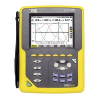
Displays phase-to-phase voltage waveforms and RMS values.

4V RMS Display Screen

Displays phase-to-neutral voltages and neutral-to-earth voltage.

4A RMS Display Screen

Displays phase currents and neutral current.

Instantaneous Inrush Current Display

PEAK Display Screen (A1)

Harmonic Analysis

Phase-to-Neutral Voltage Harmonics

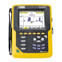
Displays harmonic levels of phase-to-neutral voltage.

Phase-to-Neutral Voltage Harmonics Display

Example screen for displaying 3L phase-to-neutral voltage harmonics.

Phase-to-Phase Voltage Harmonics Display

Current Harmonics

Current Harmonics Display

Example screen for displaying 3L current harmonics.

Apparent Power Harmonics

Apparent Power Harmonics Display

Example screen for displaying 3L apparent power harmonics.

Phase-to-Phase Voltage

Phase-to-Phase Voltage Harmonics Display

Example screen for displaying 3L phase-to-phase voltage harmonics.

Expert Mode

Phase-to-Neutral Voltage Expert Mode

Displays harmonic influence on neutral heating and rotating machines.

Current Expert Mode Display

Waveform Display

Measurement of True RMS Value

Displays waveforms and true RMS voltage and current values.

Neutral RMS Display Screen

Measurement of Total Harmonic Distortion

THD Display Screens

Displays phase-to-phase and phase-to-neutral voltage THD values.

Peak Factor Measurement

Measurement of Extreme and Mean Voltage and Current

Simultaneous Display of Measurements

Display of Fresnel Diagram

Alarm Mode

Displaying Campaigns and Alarms

Trend Mode

Programming and Starting Recording

Steps to program and initiate a trend recording session.

Trend Mode Configuration

Specifying or modifying trend recording configurations.

Viewing and Deleting Recordings

Trend Curves Display

Power and Energy Mode

Energies Consumed and Generated Displays

L1, L2, L3 Filter Power and Quantity Displays

L1, L2, L3 Energy Meters Display

Filter Sigma (Σ) Power and Quantity Displays

Filter Sigma (Σ) Energy Meters Display

Starting Energy Metering

Energy Metering Disconnection and Reset

Screen Snapshot Mode

Data Export Software

General Specifications

Power Supply Specifications

Functional Characteristics

Maintenance

Memory Card, Metrological Check, and Repair

Warranty Information

To Order

Related product manuals