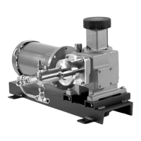
1250E & 1500E Electric Pump
Operating Manual
CP/MAN-PRD-1215E REV. 02 EFF. DATE: 12/15/12 Page 8 of 13
9.3. Open the chemical supply block valve.
9.4. Open the process block valve.
CAUTION: OTHER THAN DURING BRIEF TESTING, NEVER OPERATE THE PUMP WITHOUT
CHEMICAL SUPPLY AVAILABLE AND FLOWING FREELY. DOING SO WILL
CREATE UNDUE FRICTION AND HEAT, DECREASING THE LIFE OF THE
PACKING, HASTENING CHEMICAL LEAKAGE, AND VOIDING THE PUMP
WARRANTY.
9.5. Start the pump.
9.6. Adjust the stroke length to maximum.
9.7. Open the bleed screw 1 1/2 to 2 turns. The pump will begin to pull air and chemical through the
chemical supply plumbing, into the head, and out the port in the bleed valve. Leave the valve open
until a solid stream of chemical pumps out the bleed port with each stroke of the pump.
NOTE: If the pump is not new, it is very possible for dried or solidified chemical to be present
in the bleed assembly. If your pump does not bleed when following the directions
above, try cleaning these items in solvent and replacing them.
9.8. Close the bleed screw until chemical flow through the bleed port stops.
CAUTION: DO NOT OVER-TIGHTEN THE BLEED SCREW. TIGHTEN THE BLEED SCREW
ONLY UNTIL CHEMICAL STOPS FLOWING. APPLYING EXCESS TORQUE TO THE
BLEED VALVE MAY IMPAIR FUTURE VALVE OPERATION.
NOTE: Occasionally, soon after closing the bleed assembly, you may observe packing
leakage. If so, this is usually due to a loose packing nut. Adjust the packing nut per
the instructions in Section 11: Packing Adjustment.
9.9. Adjust the stroke length to obtain proper delivery volume per directions in Section 10 below.
10. SETTING AND ADJUSTING THE PUMP DELIVERY VOLUME
10.1. The pump stroke rate remains constant regardless of delivery volume.
10.2. The pump stroke rate is determined by the gear ratio of the gearbox and the motor speed in
revolutions per minute. To calculate the stroke rate of the pump, divide the motor speed on the
faceplate of the electric motor by the gear reduction factor of the gearbox. The gear reduction
factor is shown on the PUMP DATA SHEET.
10.3. The pump delivery volume is adjusted by changing the stroke length.
10.4. The large black dial (Item 8 on Figure 5 at the end of this Manual) is used to adjust the stroke
length of the pump.
10.5. Turning the knob adjusts the stroke length from a maximum of 15 mm (0.591 in) to a minimum of
no stroke at all.
10.6. Use the Adjustment Gauge (Item 9 on Figure 5 at the end of this Manual) on the side of the
vertical stem just underneath the black dial to determine the stroke length.