Chenbro SR209/105/107/108
4-Ports Mini-SAS Backplane User’s Manual
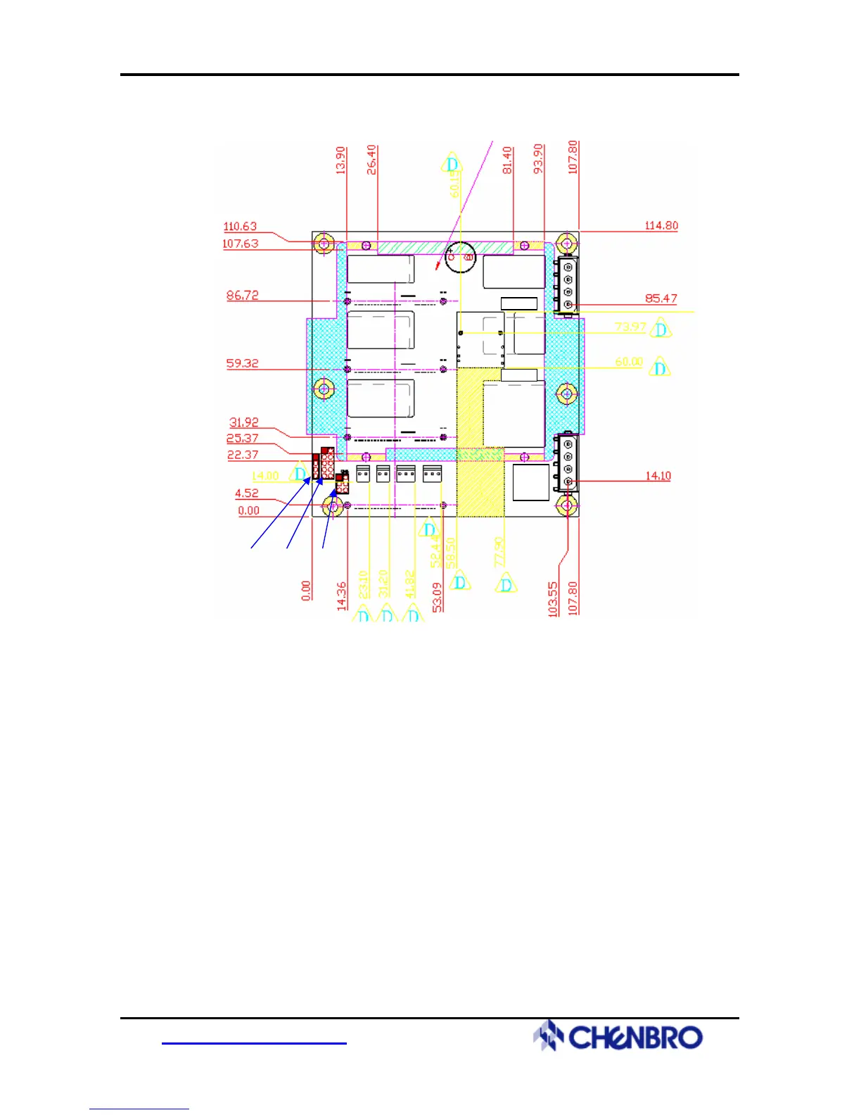
Rear View (Host Connector In )
CN3
JC1
CN7
CN9
CN4
JP1 JF1
SW1
CN2 CN1 CN5
JM1 JF2
(1) [CN11/CN21/CN31/CN41] : 29-pins SAS HDD connector
(2) [CN7] : Min-SAS Host connector
(3) [CN3 /CN4] : Power connectors
(4) [CN1] : External HDD Activity LED Signal Input connector (from RAID Card)
(5) [CN2] : HDD Fail LED Signal Input connector (from RAID Card)
(6) [CN5] : Fan/PWR/Temp. Fail LED output connector (to Front Panel LED Display)
(7) [JF1/JF2] : Fan connectors
(8) [SW1] : Functionality / Mode Setting
(9) [JP1] : Power Failure Input (From Redundant Power Supply)
(10) [JM1] : Power Failure Alarm Mute Output (to Redundant Power Supply)
(11) [JC1] : I2C connector for HDD Fail (from RAID Card)
(12) [CN9] : pin header for SGPIO enable/disable jumper setting
http://www.chenbro.com
7