Do you have a question about the Chenbro SR30169 Plus and is the answer not in the manual?
Provides backplane features, jumper settings, and pin definitions. Mentions technical contacts.
Details modifications for SR301 Plus, tool-less trays, and PCI-e 3.0 slot.
Lists supported features like 6/12Gb/s SAS/SATA, hot-swap, temp monitoring, fan control.
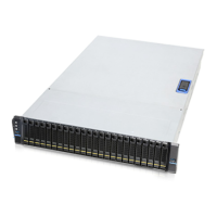
Lists compatible chassis for the backplane, specifically SR30169 Plus.
Provides diagrams showing the physical dimensions of the backplane.
Lists connectors, headers, and jumpers with their locations on the component and solder sides.
Details four SFF-8482 connectors for SATA/SAS drives supporting hot-swap functionality.
Explains the mini-SAS HD connector for connecting to a mainboard or HBA for signal integrity.
Describes the 4-pin PWM fan header for chassis fan power and monitoring, alternative to motherboard connection.
Covers jumper settings for configuring HDD access LED and fail LED modes (HDD access vs. SGPIO).
Details two connectors for powering four 3.5" hard disks, ensuring stable power input.
Explains the I2C connector for monitoring HDD temperature and fan status, noting vendor dependency.
Discusses the pin header for the event LED and mute switch, used for configuration.
Explains the DIP switch for controlling on-board hardware monitor functions like PWM fan, temperature, and buzzer.
Outlines methods for technical support inquiries: phone, email, and web.
Provides regional phone numbers for reaching Chenbro support engineers.
Gives the email address for technical inquiries and expected response via email or call.
Guides users on how to submit inquiries through the Chenbro website's support section.
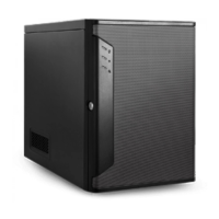
| Form Factor | Mini-ITX |
|---|---|
| Drive Bays | 4 x 3.5" |
| Material | Steel |
| Motherboard Support | Mini-ITX |
| Power Supply | 1U |
| Expansion Slots | 1 |
| Dimensions (HxWxD) | 260mm x 210mm x 270mm |