Table 10. Pin assignment of I2C connector
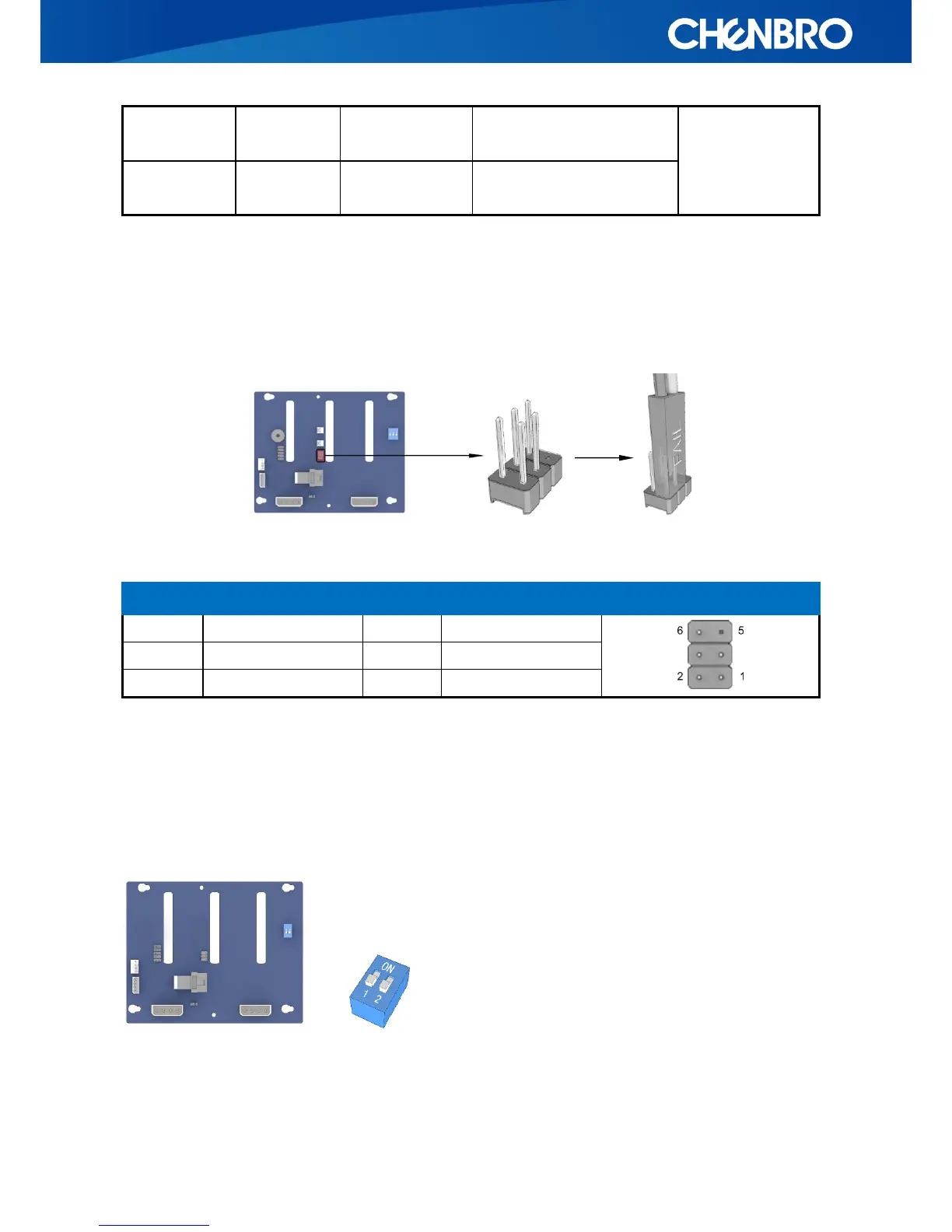
3.7 Hardware Monitor Display Pin Header (JP02)
The event LED, with red/black wire, is located on front bezel of SR301+, and can be configured
through this pin header.
Table 11. Event Warning LED and Mute Header
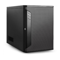
3.8 Hardware Monitor DIP Switch (SW1)
The settings of on-board hardware monitor can be controlled and configured through this DIP
switch. It can manages the functions of PWM fan, temperature threshold, and buzzer alarm.
SW1-1: FAN Control Enable/Disable Setting
If the chassis fan is powered by motherboard, this fan monitoring must be disabled.