4-port 12Gb/s SAS/ SATA Backplane - 80H10230101A0 User Manual
Chapter 2. Backplane Physical Layout
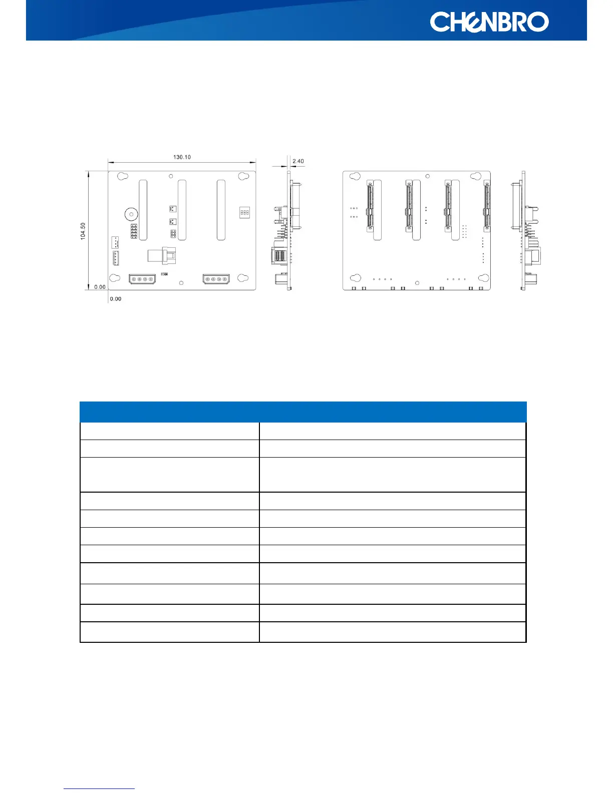
2.1 Backplane Dimension
2.2 Connector Layout
The following table is a list of all connectors, headers and jumpers applied to this backplane. With
layout diagrams, user can find where they are on both component and solder sides.
Table 3.Backplane Connector & Component Layout
Backplane Connector & Component Layout
CH011 / CH021 / CH031 / CH041
Connect to 29-pin SAS or 22-pin SATA HDD
LD011 / LD021 / LD031 / LD041
Blue LED, indicates HDD is present and powered
LD012 / LD022 / LD032 / LD042
Blinking Green LED indicates HDD activity
Solid Red LED stands for HDD failure.
Jumper for HDD Access/SGPIO modes
4-pin peripheral power connector
I2C connector, IPMI compliant
Pin header, Fail LED& Mute settings
DIP switch for hardware monitoring