Do you have a question about the Chenbro SR301 Plus series and is the answer not in the manual?
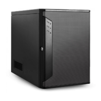
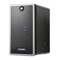
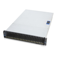
Details the external components and interfaces of the front of the server chassis.
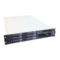
Describes the rear connections, including PSU and I/O ports, and expansion slot openings.
Outlines physical security mechanisms like padlock loops and key locks for the chassis.
Explains the function of buttons and LEDs on the front panel for system control and status.
Provides the physical dimensions of the server chassis for integration and space planning.
Shows an internal view of the chassis, highlighting key components like the HDD cage and PSU.
Lists operating and non-operating environmental parameters like temperature, humidity, and vibration.
Details the system's packaging for shipping, including part numbers and support levels.
Instructions on how to install and secure the side covers of the server chassis.
Steps for attaching and detaching the front bezel of the server chassis.
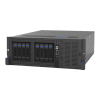
Guidance on inserting and removing 3.5" hot-swap HDD trays.
Procedures for installing, removing, and maintaining the HDD fan assembly.
Steps for installing a single power supply unit (PSU) into the chassis.
Lists available backplane options for storage devices and their common features.
Detailed specifications and connector layout for the Mini-SAS HD backplane.
Detailed specifications and connector layout for the SAS/SATA backplane.
Procedure for handling Defect On Arrival (DOA) products and warranty claims.
Information required for technical support and contact details for regional offices.