SR301 Plus Series
│ 23
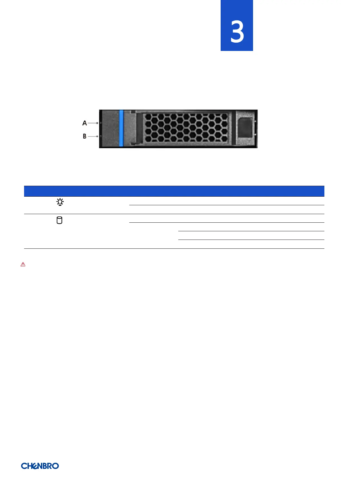
3. Backplane
Each drive tray includes separate LED indicators for drive activity and drive status. Light pipes integrated into the drive tray assembly
direct light emitted from the LEDs mounted next to each drive connector on the backplane to the drive tray faceplate, making them
visible from the front of the system.
Figure 21 Drive tray LED identification
Table 6 Drive power LED/activity LED behavior
NOTE: The drive activity LED is driven by signals coming from the drive itself. Drive vendors may choose to operate the activity
LED differently from what is described in the table above. Should the activity LED on a given drive type behave differently than
what is described, customers should take the driver vendor specifications as a reference for the specific drive model to determine
what the expected drive activity LED operation should be.