- 32 -
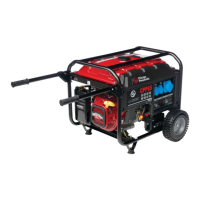
Options available for CPG 20 and CPG 25 units
Circuit diagrams
The engine control circuit diagrams and the power circuit
diagrams for the standard CPG 20 and CPG 25 units:
Power circuit
Unit Circuit
CPG 20-25 Kd 1310 3200 03
CPG 20-25 Kd - 1 phase 1310 6000 26
Engine circuit
Unit Circuit
CPG 20-25 Kd 1310 3200 08
Controller circuit
Unit Circuit
CPG 20-25 Kd Qc1002™ 1310 3200 08
Overview of the electrical options
The following electrical options are available for the CPG
20 and CPG 25 units:
– Automatic battery charger
– Battery switch
– Engine coolant heater
– External fuel tank connection (with/without quick
couplings)
Description of the electrical options
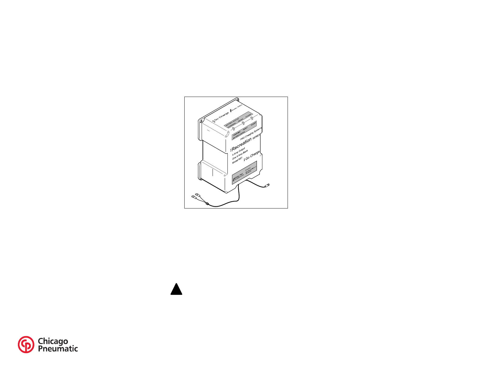
Automatic battery charger
The LED on the front indicated the battery's state of
charge.
This automatic battery charger is used for 12V system.
There are no settings required for output voltage. Just plug
it in.
– Provide the X25 connector, located at the side of the
power cubicle, with external power to use the battery
charger.
Battery switch
The battery switch is situated inside the sound-insulated
bodywork. It allows to open or to close the electrical
connection between the battery and the engine circuits.
Engine coolant heater
To make sure that the engine can start and accept load
immediately, an external coolant heater (1000 W, 120 V)
is provided which keeps the engine temperature between
38°C and 49°C.
Overview of the mechanical options
The following mechanical options are available for the
CPG 20 and CPG 25 units:
– External fuel tank connection (with/without quick
couplings)
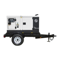
– Trailer
– The option wheel chocks allows to park the generator on
sloping ground. Place wheel chocks in front of or behind
the wheels to immobilize the generator.
Description of the mechanical options
External fuel tank connection (with/without
quick couplings)
The option external fuel tank connection allows to bypass
the internal fuel tank and to connect an external fuel tank
to the unit.
Never turn the battery switch to OFF
during operation.
 Loading...