EasyManua.ls Logo

Chicago Pneumatic HP 20 User Manual

Chicago Pneumatic HP 20
67 pages
To Next Page IconTo Next Page
Page #1 background imageLoading...
Page #1 background image
ENGLISH
.
Cod. 9828093300 00 - Vers. 04/2019 - 1
USE & MAINTENANCE MANUAL
QUIET ROTARY SCREW AIR COMPRESSORS
HP 20 - 25 - 30 - 35 KW 15 18.5 - 22 - 26
HP 20 - 25 - 30 - 35 (IVR
) KW 15 18.5 - 22 - 26(IVR
)
(IVR
): Variable speed compressors (INVERTER)
ATTENTION: THE CAPACITORS INSIDE THE INVERTER MAY REMAIN LIVE FOR 15 MINUTES AFTER THE MACHINE HAS BEEN
DISCONNECTED FROM THE MAINS POWER.
ACTING ON THE INVERTER BEFORE 15 MINUTES HAVE PASSED MAY ENTAIL THE RISK OF ELECTROCUTION AND DEATH.
CONTENTS
PART A: NOTICES FOR THE USER
PART B: NOTICES RESERVED FOR PROFESSIONALLY QUALIFIED
PERSONNEL
1.0 GENERAL CHARACTERISTICS
20.0 START-UP
2.0 INTENDED USE
21.0 GENERAL ROUTINE MAINTENANCE REQUIRES TRAINED
PERSONNEL
3.0 OPERATING PRINCIPLE
22.0 OIL REPLACEMENT
4.0 GENERAL SAFETY REGULATIONS
23.0 OIL FILTER AND OIL SEPARATOR FILTER
REPLACEMENT
5.0 DESCRIPTION OF HAZARD SYMBOLS
24.0 MOTOR BEARING GREASING (IVR ONLY)
6.0 HAZARDOUS AREAS
25.0 OLEO-PNEUMATIC DIAGRAM
7.0 SAFETY DEVICES
26.0 DRYER CALIBRATIONS
8.0 POSITION OF LABELS
27.0 VARIABLE SPEED (IVR)
9.0 COMPRESSOR ROOM
10.0 TRANSPORT & HANDLING
11.0 UNPACKING
ATTENTION: A COPY OF THE WIRING DIAGRAMS IS INCLUDED IN
THE ELECTRICAL CABINET OF THE COMPRESSOR
12.0 INSTALLATION
13.0 OVERALL DIMENSIONS AND TECHNICAL DATA
14.0 ILLUSTRATION OF MACHINE
15.0 ROUTINE MAINTENANCE BY THE USER
16.0 STORAGE
17.0 DISMANTLING THE AIR COMPRESSOR
18.0 SPARE PARTS LIST FOR ROUTINE MAINTENANCE
19.0 TROUBLESHOOTING AND IMMEDIATE ACTIONS
Code
9828093300
00
Vers. 04/2019
READ THIS MANUAL CAREFULLY BEFORE PERFORMING ANY OPERATIONS ON THE AIR COMPRESSOR.
THIS MACHINE IS DESIGNED TO BE CONNECTED TO TWO DIFFERENT SOURCES OF ELECTRICAL POWER: THREE-PHASE
POWER SOURCE FOR COMPRESSOR, SINGLE PHASE POWER SOURCE FOR DRYER

Table of Contents

Question and Answer IconNeed help?

Do you have a question about the Chicago Pneumatic HP 20 and is the answer not in the manual?

Chicago Pneumatic HP 20 Specifications

General IconGeneral
BrandChicago Pneumatic
ModelHP 20
CategoryAir Compressor
LanguageEnglish

Summary

General Characteristics

4.0 GENERAL SAFETY REGULATIONS

Outlines essential safety rules for operating the equipment.

Hazard Symbols and Areas

5.0 DESCRIPTION OF HAZARD SYMBOLS

Illustrates and explains various hazard symbols used in the manual.

Safety Devices and Labels

7.1 SAFETY DEVICES FOR SCREW COMPRESSOR

Details specific safety devices incorporated into the screw compressor.

Installation and Handling

12.1 POSITIONING

Guides the user on correctly positioning the machine for installation.

12.2 ELECTRICAL CONNECTION

Explains the critical steps for making the electrical connection safely.

Technical Specifications and Diagrams

12.3 CONNECTION TO COMPRESSED AIR DISTRIBUTION NETWORK

Describes how to connect the compressor to the compressed air network.

12.5 START-UP

Refers to Part B for the start-up procedure.

Controller Operation and Displays

14.2 CONTROL PANEL AND COMMANDS

Explains the function of the control panel and its buttons.

14.3 CONTROLLER (Standard electronic control board for fixed speed compressors)

Details the standard controller for fixed speed compressors.

Alarm and Fault Management

Alarm warnings

Explains conditions that trigger alarm warnings on the compressor.

Screw compressor output temperature

Details alarms related to high output temperature and how to check them.

Fail stops

Lists conditions that cause the compressor to stop automatically.

Output temperature from element

Explains fail stop conditions for element output temperature.

Display and Navigation

Alarm display

Explains how alarms are indicated on the display and how to check them.

Shutdown display

Details how shutdowns are shown on the display and their causes.

System Monitoring and Control

Inverter warnings and alarms

Lists and explains various inverter-related warnings and alarms.

Settings and Maintenance Programs

Routine Maintenance by User

Spare Parts and Troubleshooting

19.1 TROUBLESHOOTING AND IMMEDIATE ACTIONS FOR SCREW COMPRESSOR

Provides solutions for common problems encountered with the screw compressor.

19.3 TROUBLESHOOTING AND IMMEDIATE ACTIONS FOR DRYER

Lists common problems and solutions for the air dryer unit.

Start-Up Procedures

20.3 CHECKING THE DIRECTION OF ROTATION

Explains how to verify and correct the motor and fan rotation direction.

General Routine Maintenance

Component Replacement

22.0 OIL REPLACEMENT

Provides a step-by-step guide for replacing the compressor oil.

23.0 REPLACE THE OIL SEPARATOR FILTER AND THE OIL FILTER

Details the procedure for replacing the oil separator and oil filters.
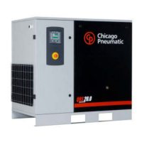
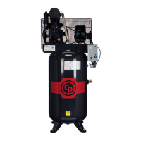
Motor Greasing and Diagrams

Related product manuals