TIL1X2AA / TIL1X3AA / TIL1X4AA / TILVABAA Installation Instructions
6
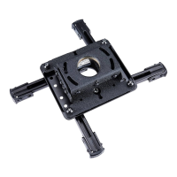
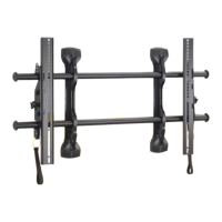
Installing First Mount
The TIL1X2AA / TIL1X3AA /TIL1X4AA (Absen Acclaim Series)
LED wall mounts are designed to be mounted to:
• a bare 8" concrete or 8"x8"x16" concrete block wall; or
• a 3/4" thickness plywood-backed, 2" x 4" wood studs
(16" on center minimum) wall with a maximum drywall
thickness of 5/8"; or
•
a 3/4" thickness plywood-backed, steel stud wall
covered with drywall having a maximum thickness of
5/8".
Table 1: Fastener Information
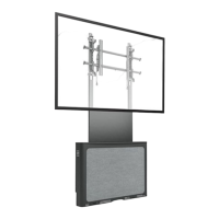
1. Hold furthest left, top wall mount against wall ensuring that
mounting slot is lined up with center line marked on the wall
in Determining Installation Site section. Double-check
with a level. (See Figure 4)
2. Mark mounting holes in two top mounting slots along the
horizontal line marked in Step 3. (See Figure 4)
NOTE: The center of the mounting holes are 14.25" apart on-
center. (See Figure 4)
Figure 4
3. Drill two pilot holes (see Table 1 for size) at each location
marked in Step 2 (See Figure 4) and follow fastener
information (appropriate for wall type) located in Table 1.
IMPORTANT ! : Refer to Fastener Installation Methods
(located in Appendix at end of Installation Instructions)
for details on installing product into various wall types.
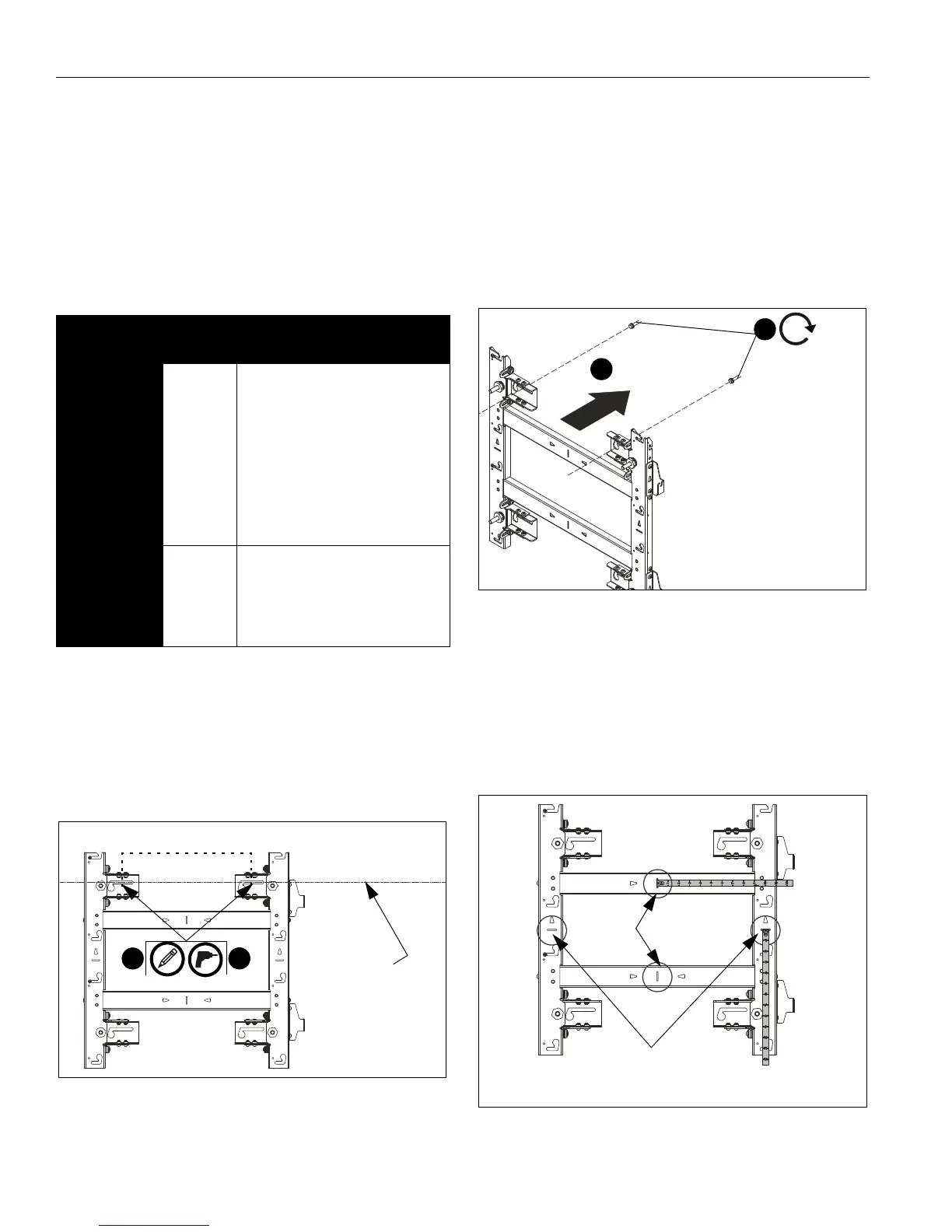
4. Partially install two fasteners into wall, but do NOT
completely tighten to wall. (See Figure 5)
NOTE: Utilizing the two U-shaped installation washers (H)
allows the installer to pre-install the top mounting
fasteners and hang the mount from them utilizing the
mount’s teardrop slots. This allows the weight of the
mount to be held by the mounting bolts and not the
installer during installation.
Figure 5
5. Hang wall mount, aligning upper teardrop slots over
fasteners, and adjust side-to-side for proper location. (See
Figure 5)
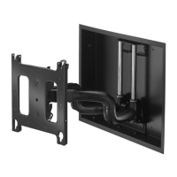
NOTE: The horizontal slots located along the vertical mount
pieces indicate the approximate center line of the two
LED modules. The vertical slots located along the
horizontal mount pieces indicate the horizontal center
line of the mount. The slots can be used to hold a tape
measure tab while measuring. (See Figure 6)
Figure 6
WALL
TYPE
PILOT
HOLE
FASTENERS (see PARTS
drawing)
Drywall
attached to
plywood-
backed walls
/Steel studs
Drywall
attached to
plywood-
backed walls
/Wood studs
1/2"
7/32" x 3"
- 1/4-20 x 2-1/2" hex head lag (not
included)
- 1/4" washer (not included)
- 1/4-20 Toggler Snaptoggle BB
(not included)
- 5/16 x 2-1/2" flanged hex head
lag (F)
- 5/16" washer (J)
- Installation washer (H)
Concrete or
concrete
block
3/8" x 3" - 5/16 x 2-1/2" flanged hex head
lag (F)
- 5/16" washer (J)
- Installation washer (H)
- Fischer Anchor UX10x60R (G)
2
14.25 inches
3
Line showing
slots for top
mounts in LED wall
center of mounting
[TIL1X2AA shown as example]
4
5
x 2
[TIL1X2AA shown as example]
Indicates
center line
of the mount
horizontal
Indicates approximate
center line between
two LED modules