Installation Instructions TIL1X2AA / TIL1X3AA / TIL1X4AA / TILVABAA
7
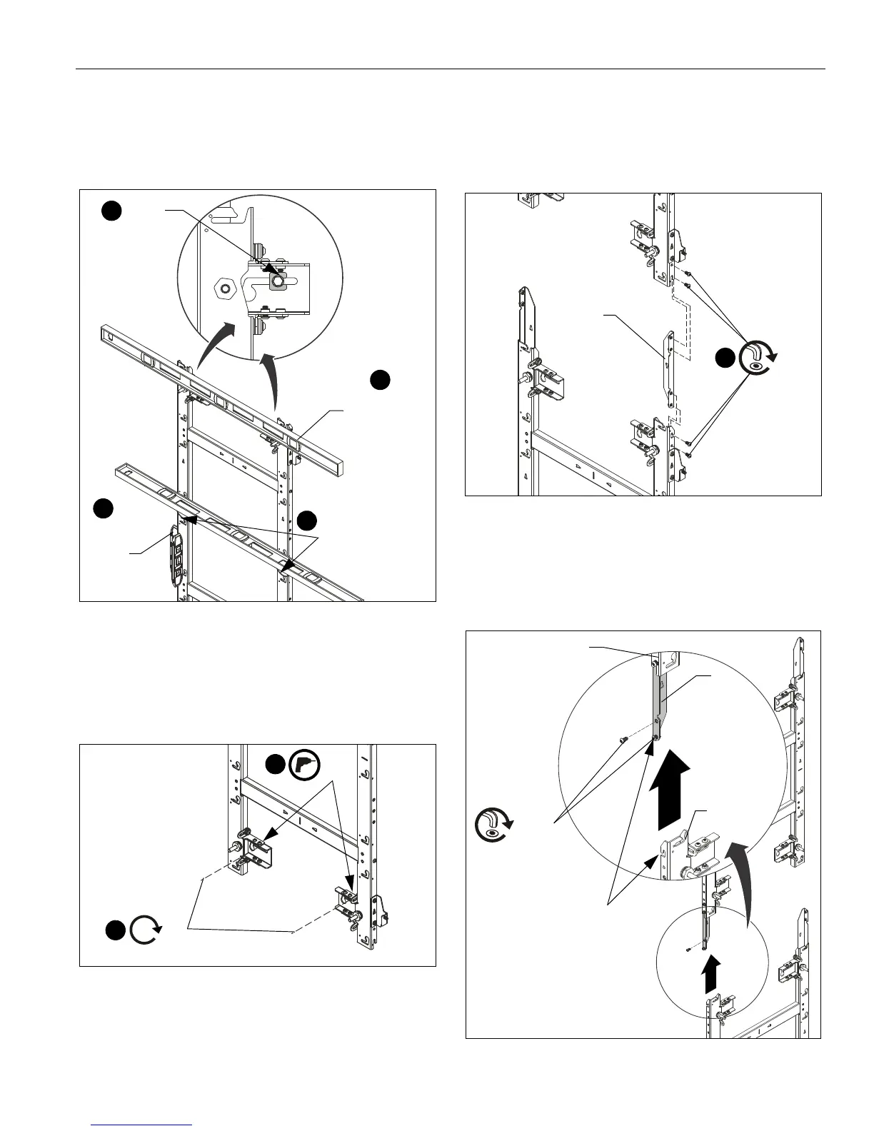
6. Lay levels across flat of the mounting holes and center line
indicators, and vertically along side of mount to ensure wall
mount is square and level. (See Figure 7)
7. Slide installation washers (H) behind head of fasteners and
tighten mount in place. (See Figure 7)
Figure 7
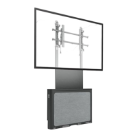
8. Drill lower pilot holes (see Table 1 for size) at attachment
locations and follow fastener information (appropriate for
wall type) located in Table 1. (See Figure 8)
9. Install two fasteners through lower part of mount and
tighten. (See Figure 8)
Figure 8
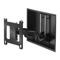
10. (OPTIONAL) If more LED housings need to be added to the
top or bottom of the screen configuration, add TILVABAA
vertical connector kit (not included) to top or bottom of wall
mount. If you are NOT adding the TILVABAA connector kit,
proceed to Step 11.
• Add the vertical connector (K) to the top or bottom of
the mount, and fasten with two 1/4-20 x 1/2" button
head cap screws (L) per vertical connector. (See
Figure 9)
• Connect another wall mount to the other end of the
vertical connector to lengthen the LED wall.
Figure 9
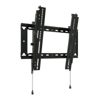
NOTE:
When connecting a mount to the bottom of an installed
mount, the lower mount may be hung by its open slot
on the partially installed button head screw (L) before
tightening the connection. (See Figure 10)
Figure 10
Level placed
across flat of
mounting holes
Level along
side of
mount
6
6
7
(H) x 2
6
Level placed along
center-of-LED
modules indicator
(L) x 2
(K)
Top
mount
Lower
mount
Hang open slot onto
partially installed button
head screw (L) and tighten
both screws (L).