TIL1X2AA / TIL1X3AA / TIL1X4AA / TILVABAA Installation Instructions
8
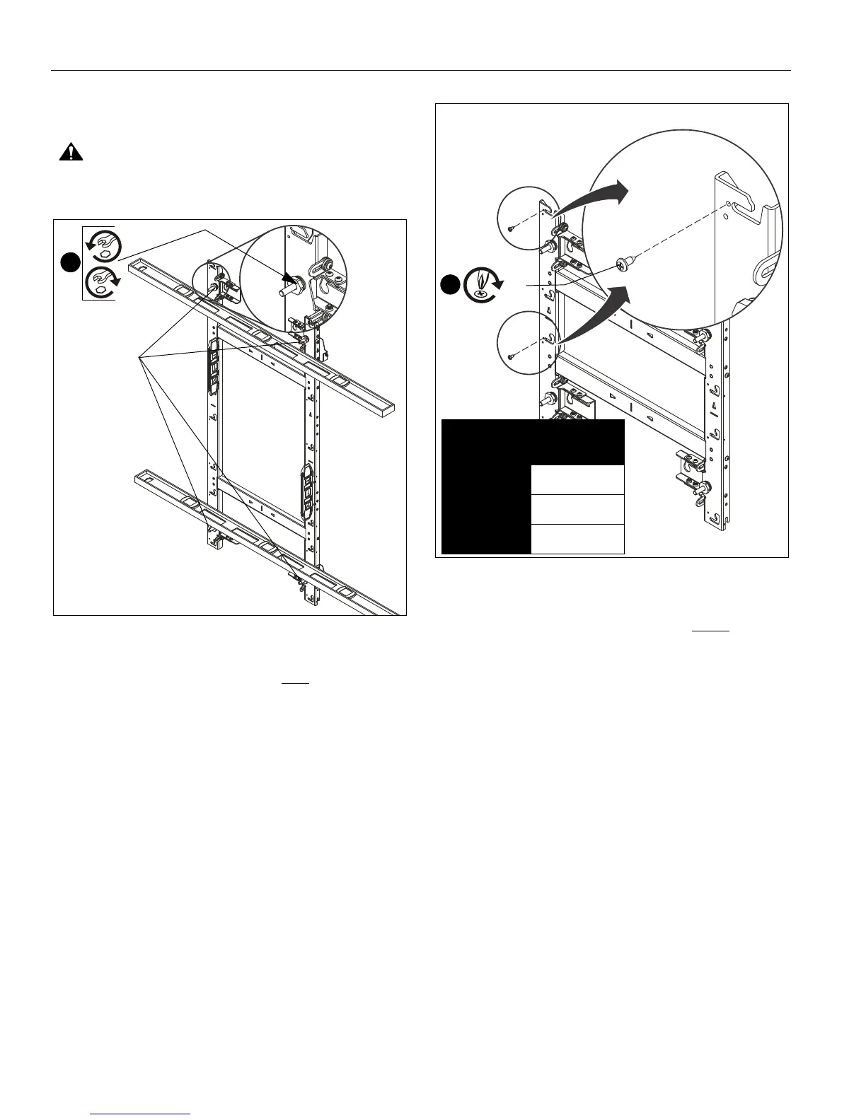
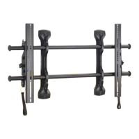
11. Using a level on the front of the mount in various places, use
a 1" socket and T-handle driver to adjust the leveling feet on
the mount until the mount is plumb. (See Figure 11)
CAUTION: Over-torquing may cause damage. Do NOT
use a drill to make the depth adjustment.
Figure 11
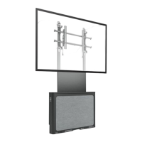
12. Install one 8-32 x 1/2" Phillips tapping screw (C) into left
upper LED mounting button hole for each LED screen
space. (See Figure 12)
Figure 12
IMPORTANT ! : The tapping screws keep the LED
modules centered on the mount, and are ONLY
installed
on the furthest left column of mounts.
NOTE: Using a drill driver makes installation of the tapping
screws (C) easier.
Model Fastener
Qty
TIL1X4AA 4
TIL1X3AA 3
TIL1X2AA 2
[TIL1X2AA shown as example]
12
(C)