Installation Instructions TIL1X2AA / TIL1X3AA / TIL1X4AA / TILVABAA
9
Adding Additional Mounts
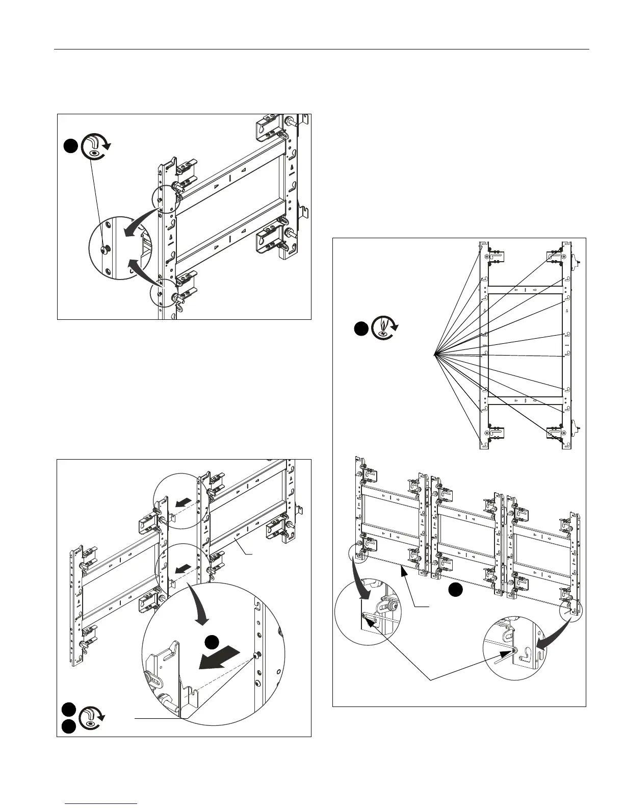
1. Partially install two 1/4-20 x 1/2" button head screws (B) into
the left side of the next mount. (See Figure 13)
Figure 13
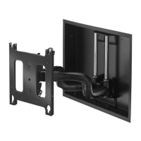
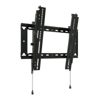
2. Connect second mount to the right side of the already
installed mount hanging it by the 1/4-20 x 1/2" button head
screws (B) onto each horizontal connector on the mounts
right side. (See Figure 14)
NOTE: For larger LED walls it is helpful to check placement
and alignment by putting a few housings in place during
the installation, checking alignment before removing
the housings, and then continuing the installation.
Figure 14
3. Use a level to align the second mount with the first mount.
4. Tighten both fasteners (where the second mount is hung on
the first mount) to fasten two mounts together. (See
Figure 14)
5. Drill pilot holes in the mounting slots and fasten the second
wall mount to the wall following the same steps as used for
the first wall mount.
6. Recheck the alignment and overall flatness of the wall
mounts during the installation process.
7. Continue the installation process until all wall mounts are
attached.
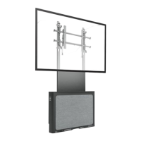
8. Install the 8-32 x 1/2" self-tapping screws (C) on the mount
to attach string for alignment. (See Figure 15)
Figure 15
9. Run a string between the self-tapping screws installed in
Step 8 to assist with alignment across long sections of
mounts. (See Figure 15)
2
(B) x 2
[TIL1X2AA shown as example]
Second
mount
2
4
String to assist
with alignment
9
[Multiple TIL1X2AA shown as example
for using string to assist with alignment.]
(C)
8
Screw holes for
attaching string are
located at each
mounting button slot
Self-tapping screws