OLCB1U Installation Instructions
8
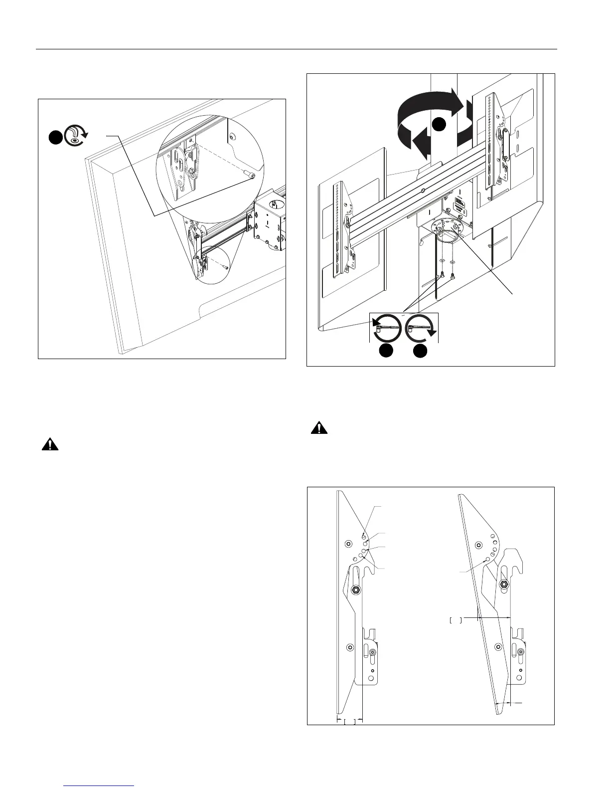
4. Fasten brackets against ceiling mount extrusion using #10-
24 x 1/2" socket head cap screws (M). (See Figure 7)
5. Repeat for other interface bracket.
Figure 7
6. Repeat Steps 1-5 to install display to the other side of the
mount.
Adjustments
CAUTION: Watch for pinch points! Do not place fingers
between movable parts.
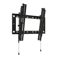
Yaw
The ceiling mounts allows yaw adjustment in 45° increments in
each direction.
1. Remove two bolts and washers connecting column collar to
mount assembly box. (See Figure 8)
2. Adjust yaw in 45° increment until desired position is
achieved. (See Figure 8)
3. Reinstall bolts and washers removed in Step 1. (See Figure
8)
Figure 8
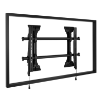
Tilt
CAUTION: Watch for pinch points! Do not place fingers
between movable parts.
The interface brackets allow -7.6° to 20° tilt, and can be locked
at -7.6°, -5°, 0°, 5°, 10°, 15° and 20° tilt. (See Figure 9)
Figure 9
4
(M)
(wind shield hidden for clarity)
1
column collar
3
2
+/- 45°
1.91
48.4
0° HOLE
LOCKOUT
+5°AND -15°
HOLE LOCKOUT
-5° AND -20°
HOLE LOCKOUT
+7.6° HOLE
LOCKOUT
- 10°
2.48
63.0
-10° HOLE
LOCKOUT