Installation Instructions OLCB1U
9
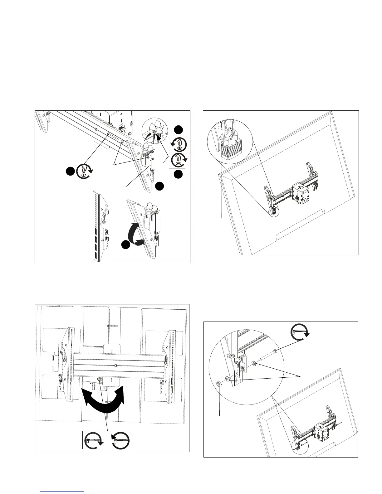
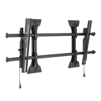
4. If necessary, loosen button head tilt friction bolt (located on
side of interface bracket). (See Figure 10)
5. Adjust tilt as required. (See Figure 10)
6. The tilt may be locked at -7.6°, -5°, 0°, 5°, 10°, 15° and 20°
using one 1/4-20 x 2" Phillips head screw (N), one 1/4-20
lock nut (Q) and two 1/4" washers (T) per interface bracket.
(See Figure 9) and (See Figure 10)
NOTE: Use of washers (T) is optional.
7. Tighten button head tilt friction bolt as necessary.
Figure 10
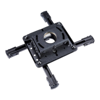
Roll
1. Adjust roll adjustment screw to change roll position.The roll
may be adjusted 3° in either direction. (See Figure 11)
Figure 11
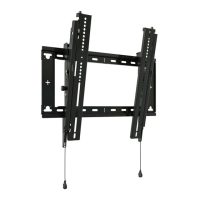
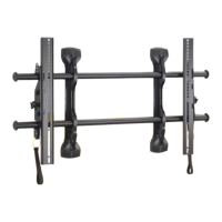
Latch Lock/Security
IMPORTANT ! : In order to prevent interface latch from
getting loose due to strong winds, the latch MUST be
locked either using a padlock or locking bolt (N) and 5/
16-18 hex nuts (Q). This is NOT optional!
Using Padlocks (Security)
1. Add padlock (not included) to each interface bracket to lock
latch and to provide security for displays. (See Figure 12)
Figure 12
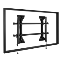
Using Bolts/Nuts
NOTE: This will keep latch from opening but does not provide
additional security for the displays.
1. Use 5/16-18 x 2" hex head carriage bolt (P), 5/16-18 hex nut
(R) and two 5/16" washers (S) to lock each interface bracket
latch in place. (See Figure 13)
Figure 13
Tilt
friction
bolt
4
4
7
6
(N)
(Q)
0° tilt
20° tilt
5
(T) x 2
roll adjustment screw
or
Padlock
(Optional)
(P)
(R)
(S) x 2