Do you have a question about the Chigo CMV-MINI and is the answer not in the manual?
| Brand | Chigo |
|---|---|
| Model | CMV-MINI |
| Category | Air Conditioner |
| Language | English |
Checking for transport damage, type, specification, quantity, and accessories.
Guidelines for installing refrigerant pipes, including diameter, welding, and insulation.
Procedure for a 24-hour air tightness test using nitrogen.
Vacuumizing the system after the air tightness test.
Calculating and recording refrigerant refilling volume and pipe details.
Selecting power supply capacity, wire diameter, and avoiding wire interlacing.
Trial run requirements, stating it cannot be performed until the outdoor unit is powered on for 12 hours.
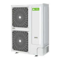
Criteria for choosing the outdoor unit installation location for optimal performance and maintenance.
Provides dimensions for 10.5kW and 14/16kW outdoor units.
Safe procedures and precautions for hoisting the outdoor unit, including rope usage and inclination.
Requirements for foundation and space around the unit for installation and maintenance.
How to connect pipes for 10.5kW and 14/16kW models, including outlet routing.
Procedures for cutting, flaring refrigerant pipes, fastening nuts, and ensuring proper torque to prevent leakage or damage.
Table specifying required pipe diameter based on outdoor unit capacity and pipe length.
Cleaning the refrigerant pipe with high-pressure nitrogen, avoiding oxygen or flammable gases.
Performing a 24-hour air tightness test after connecting pipes, checking for pressure drops.
Procedures and requirements for vacuumizing the system using a suitable vacuum pump.
Calculating and weighing refrigerant (R410A) for refilling in liquid state.
Instructions on operating stop valves and using special tools for vacuumizing and refilling.
Guidelines for applying thermal insulation to gas and liquid pipes, including material specifications.
Details power supply, wire size, breaker ratings, and connection notes for outdoor unit wiring.
Instruction to refer to the unit's side plate for the electrical wiring diagram.
Refers to the configuration settings on the main control board.
Lists various spot-check contents and their corresponding numbers for monitoring unit status.
Lists fault codes, their contents, and remarks for troubleshooting unit issues.
Pre-debugging checks including pipeline, communication lines, power supply, and system vacuumization.
Steps before debugging, such as calculating refrigerant, preparing tools, and setting addresses.
Naming and recording connecting systems for identification, especially with multiple indoor units.
Safety measures and calculations for refrigerant concentration limits and leak prevention.
Procedures for handing over the manual and explaining its contents to the client.