Do you have a question about the Chigo CS-51H3A-P85AH4A and is the answer not in the manual?
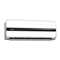
Displays images and identifies the indoor unit models.
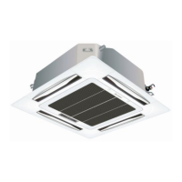
Displays images and identifies the outdoor unit models.
Lists critical safety instructions to prevent harm and damage.
Alerts users about specific installation dangers and incorrect operations.
Details wrench torque, cable connection, and pipe length/elevation specs.
Emphasizes adequate space for installation and ongoing maintenance.
Specifies height restrictions for indoor and outdoor units.
Illustrates specific clearance requirements around the outdoor unit.
Details the process of fixing the wall-mounting plate securely.
Instructs on drilling holes for water drainage with specific dimensions.
Guides on installing the drain pipe correctly to prevent water issues.
Explains how to hang the indoor unit onto the wall-mounting plate.
Lists checks for proper installation of indoor unit components.
Shows dimensions for installing parallel units.
Details the procedure for vacuum purging the air conditioner system.
Explains how to check for gas leaks after pipeline connection.
First step in connecting pipelines for whole-unit quick coupler models.
Second step for connecting pipelines for whole-unit quick coupler models.
Third step for connecting pipelines for whole-unit quick coupler models.
Fourth step for connecting pipelines for whole-unit quick coupler models.
Fifth step for connecting pipelines for whole-unit quick coupler models.
Final step for connecting pipelines for whole-unit quick coupler models.
Presents detailed specifications for various models, including electrical and physical parameters.
Provides circuit diagrams for various indoor unit models.
Circuit diagram for CS-61H3A-P85AE2 model.
Circuit diagram for CS-70H3A-T**AS model.
Circuit diagram for KFR-70GW/X1c model.
Schematic diagram for 38-section crystal color ordinary PCB.
Schematic diagram for 65-model Mitsubishi main chip PCB.
Schematic diagrams for 85-section models.
Schematic for 18NV 85 compatible electrically controlled diagrams.
Describes the function of two specific LEDs on the display panel.
Describes the function of eleven LEDs on the display panel.
Explains the function of two LEDs and two 8-LED displays.
Details the multi-colour LED panel display modes.
Explains the intelligent defrost process based on temperature comparisons.
Details defrost conditions controlled by the outdoor PCB.
Conditions for initiating the defrost cycle.
Conditions for ending the defrost cycle.
Visual sequence of operations during defrost mode.
Explains failure codes and solutions for the DF indicator.
Explains failure codes and solutions for the E2 indicator.
Explains failure codes and solutions for the E3 indicator.
Explains failure codes and solutions for the E4 indicator.
Explains failure codes and solutions for the E5 indicator.
Explains failure codes and solutions for the E6 indicator.
Explains failure codes and solutions for the E7 indicator.
Explains failure codes and solutions for the E8 indicator.
Troubleshooting steps for indoor temperature sensor errors.
Troubleshooting steps for indoor coil pipe temperature sensor errors.
| Power Supply | 220-240V, 50Hz |
|---|---|
| Type | Split |
| Cooling Capacity | 5100 W |
| Heating Capacity | 5100 W |
| Power Input (Cooling) | 1600 W |