EasyManua.ls Logo

Chigo CS-35H3A-M85AH4 User Manual

Chigo CS-35H3A-M85AH4
104 pages
To Next Page IconTo Next Page
Page #1 background imageLoading...
Page #1 background image
1
CHIGO
Service mannal
Room airconditioner
Split Wall-Mounted Type
NOTE:
Before servicing the unit, please first read the service
manual and then contact with your service center if
meet problem

Table of Contents

Question and Answer IconNeed help?

Do you have a question about the Chigo CS-35H3A-M85AH4 and is the answer not in the manual?

Chigo CS-35H3A-M85AH4 Specifications

General IconGeneral
RefrigerantR410A
TypeSplit System
Cooling Capacity3500 W
Heating Capacity3500 W
Operating Temperature (Cooling)18-43 °C
Operating Temperature (Heating)-7°C ~ 24°C

Summary

CHIGO Service Manual

Room Air Conditioner - Split Wall-Mounted Type

Introduction to the service manual for split wall-mounted air conditioners.

1. Summary

1.1 Indoor Unit Specifications

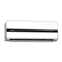
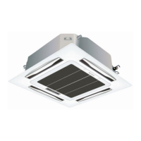
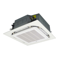
Technical specifications for various indoor unit models.

1.2 Outdoor Unit Specifications

Technical specifications for various outdoor unit models.

2. Model Explaining

3. Installation Attention

Important safety precautions and warnings regarding the installation process.

3.1 Safety Precaution

3.2 Warning

Important warnings related to installation procedures and component use.

Safety Precautions and Warnings

Cautions and Operational Guidelines

CAUTIONS

Cautions to be observed during installation and operation to prevent issues.

OPERATIONAL GUIDELINES

Guidelines for operating the air conditioner safely and effectively.

3.3 Installation Details

Wrench Torque Sheet

Table specifying torque values for installation fasteners.

Connecting Cables and Pipe Specifications

Guidelines for electrical connections and refrigerant pipe dimensions/elevation.

Foreword

Installation & Repair Guide - Indoor Unit

Indoor Unit Installation Positions

Criteria for selecting optimal indoor unit mounting locations.

Space for Installation and Maintenance

Requirements for adequate space for unit installation and servicing.

Height Limits

Maximum permissible height difference between indoor and outdoor units.

Installation & Repair Guide - Outdoor Unit

Outdoor Unit Installation Positions

Guidelines for selecting appropriate locations for the outdoor unit.

Outdoor Unit Space Requirements

Detailed specifications for clearance around the outdoor unit.

Indoor Unit Installation Procedures

Mounting Fixtures and Wall Plate

Instructions for installing mounting brackets and the wall plate for the indoor unit.

Pipe and Drain Installation

Guidance on drilling holes and installing refrigerant pipes and drain.

Indoor Unit Mounting and Securing

Procedures for hanging and securing the indoor unit onto the wall mount.

Outdoor Unit Installation and Piping

Outdoor Unit Installation Fixtures

Procedures and precautions for installing the outdoor unit.

Ordinary Pipelines Connection & Air Purging

Standard procedure for connecting refrigerant pipes and purging air.

Refrigerant Piping Installation Details

Wrench Torque for Connections

Table specifying torque values for pipe connections.

Vacuum Pump Air Purging

Steps for evacuating the refrigerant system using a vacuum pump.

Gas Leakage Inspection

Split Type Quick Coupler Model Pipelines

Whole-Unit Type Quick Coupler Pipelines

Power Cable Connection

Finishing Touches and Test Running

Installation Verification and Maintenance

Correct Installation Check

Checklist to confirm the unit is installed correctly.

Operation Noise Considerations

Guidance on managing and minimizing operational noise.

Inspection and Maintenance Schedule

Recommendations for periodic inspections and maintenance.

Self-Diagnosis Functions

Quick Connector Installation Instructions

General Installation Guide

Unit Components and Working Principle

Explosion Diagrams and Spare Parts

Reference to diagrams and parts lists for indoor/outdoor units.

Refrigerant Cycle Diagram

Illustration of the refrigerant flow and working principle.

6. Parameters

Table 6-1: Unit Parameters

Detailed technical parameters for various unit models.

Table 6-2: Model Specifications

Table 6-23: Model Specifications

Compressor Specifications

7. Wiring Diagrams

7.1 Indoor Unit Wiring Diagrams

Circuit diagrams for various indoor unit models.

Indoor Unit Wiring Diagrams (Continued)

Indoor Unit Wiring Diagrams (Continued)

7.2 Outdoor Unit Wiring Diagrams

Outdoor Unit Circuit Diagrams

Circuit diagrams for various outdoor unit models.

8. PCB Principle Charts

8.1 38-Section Crystal Color Schematic

Schematic for the 38-section crystal color PCB.

8.2 Mitsubishi Main Chip Schematic

Schematic for the Mitsubishi main chip PCB (65 model).

8.3 Schematic Diagrams

8.4 18NV 85 Electrically Controlled Schematics

Schematics for the 18NV 85 model's control system.

8.5 Mitsubishi 85 Model Control Boards

9. PCB Functionality

Display Panel Indicators

Explanation of display panel indicators (LEDs) and their functions across different configurations.

Cooling Operation Modes

Heating Operation Modes

Defrost Function (Heating Mode)

Intelligent Defrost Operation

1. Intelligent Defrost

Explanation of the intelligent defrost mechanism and conditions.

2. Outdoor PCB for Defrost

Role of the outdoor PCB in the defrost process.

Defrost Conditions and Sensors

Unit Start Defrost Conditions

Conditions required for initiating the defrost cycle.

End Defrost Conditions

Criteria for concluding the defrost cycle.

Outdoor Defrost Sensor

Information regarding the outdoor sensor for defrost.

Defrost Sequence Conditions

Unit Start Defrost Conditions

Conditions required for initiating the defrost cycle.

End Defrost Conditions

Criteria for concluding the defrost cycle.

Defrost Mode Sequence Chart

Dehumidification Mode

Ventilation Mode

Automatic Operation Mode

Operational Features

Time On/Off Function

Explanation of the timer features for unit operation.

Sleep Mode Function

Details on the sleep mode and its effects.

Emergency Key Function

Information on the emergency key for manual control.

Failure Display Codes

Table explaining LED indicators and corresponding fault codes.

Failure Display Codes (Continued)

LED Lamp Display Codes

Table explaining LED indicators and corresponding fault codes.

Failure Display Codes (Continued)

LED Lamp Display Codes

Table explaining LED indicators and corresponding fault codes.

10. Troubleshooting

Indoor Sensor Error Troubleshooting

Steps to resolve errors related to indoor temperature sensors.

Indoor TP1 Sensor Error Troubleshooting

Troubleshooting steps for indoor coil pipe temperature sensor errors.

Indoor Fan Motor Troubleshooting

Primary Checks for Fan Motor

Initial checks for indoor fan motor non-operation.

Compressor Troubleshooting

Primary Checks for Compressor

Initial checks for compressor non-operation.

Unit Operation and Indicator Issues

Troubleshooting Transmission and Receiver Issues

Steps for issues with transmission marks, batteries, and receiver signals.

General Troubleshooting Guide

Display and Unit Operation Checks

Steps to verify display and unit operational status.

Outdoor Unit and Compressor Checks

Diagnostic steps for outdoor unit and compressor operation.

Indoor Unit and Control Checks

Checks for indoor unit operation and control board functionality.

Unit Non-Operation Troubleshooting

Power Supply and Switch Checks

Checks related to power supply, switches, and wiring.

Related product manuals