Do you have a question about the Chigo CS-25V1A-H1; CS-35V1A-E2; CS-50V9A-S; CS-70V9A-T and is the answer not in the manual?
| Refrigerant | R410A |
|---|---|
| Power Supply | 220-240V, 50Hz |
| Model | CS-25V1A-H1 |
| Cooling Capacity (CS-25V1A-H1) | 2.5 kW |
| Cooling Capacity (CS-35V1A-E2) | 3.5 kW |
| Cooling Capacity (CS-50V9A-S) | 5.0 kW |
| Cooling Capacity (CS-70V9A-T) | 7.0 kW |
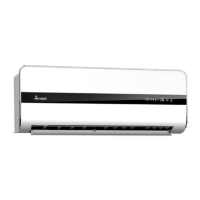
| Type | Split System |
Details of DC Inverter single series air conditioning units, including cooling and heat pump types.
Standard operating conditions for cooling and heating based on ANSI/AHAM RAC-1-2003.
Defines the upper and lower operating limits for cooling and heating.
Guidelines to prevent motor demagnetizing, including current and temperature limits.
Graph illustrating the relationship between compressor operating frequency and condensing pressure.
Graph illustrating cooling capacity correction factor based on outdoor temperature.
Graph illustrating heating capacity correction factor based on outdoor temperature.
Graph showing cooling capacity correction factor based on tubing length.
Graph showing heating capacity correction factor based on tubing length.
Graph displaying suction pressure versus outdoor dry bulb temperature for cooling.
Graph displaying discharge pressure versus outdoor dry bulb temperature for cooling.
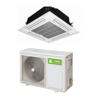
Physical dimensions and specifications for the CS-25V1A-H1 outdoor unit.
Physical dimensions and specifications for the CS-35V1A-E2 outdoor unit.
Physical dimensions and specifications for the CS-50V9A-S outdoor unit.
Physical dimensions and specifications for the CS-70V9A-T outdoor unit.
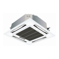
Diagrams and dimensions for indoor unit installation and body size.
Exploded view and list of spare parts for the CS-25V1A-H1 model.
Exploded view and list of spare parts for the CS-25V1A-M81A model.
Exploded view and list of spare parts for the CS-35V1A-E2 model.
Exploded view and list of spare parts for the CS-35V1A-P81A model.
Exploded view and list of spare parts for the CS-50V9A-S model.
Exploded view and list of spare parts for the CS-50V9A-S81A model.
Exploded view and list of spare parts for the CS-70V9A-T model.
Exploded view and list of spare parts for the CS-50V9A-S model.
Detailed diagnosis and causes for various indoor unit malfunctions and error codes.
Analysis and resolution steps for F1 communication error codes.
Analysis and resolution steps for F2 indoor temperature sensor faults.
Analysis and resolution steps for F3 indoor coil temperature sensor faults.
Analysis and resolution steps for F4 indoor fan motor faults.
Analysis and resolution steps for F6 outdoor temperature sensor faults.
Analysis for FA communication faults between wire controller and indoor PCB.
Analysis for P2 outdoor unit transducer module protection faults.
Analysis for P3 faults related to large indoor input current.
Analysis for P4 faults related to high discharge temp or ambient temp.
Analysis for P7 faults related to abnormal outdoor DC voltage.
Analysis for P8 faults related to refrigerant or valve issues.
Analysis for FF faults concerning the outdoor unit.
Analysis for FC faults related to outdoor unit drive and compressor start.