Page 4 of 16 IRIS Touch Quick Installation & Maintenance Guide Version 1.1
3. Package Contents
Contents dependent on model type:
• Dialler board
• Ethernet cable (IRIS Touch 620 & 640)
• GSM antenna (IRIS Touch 600 & 640)
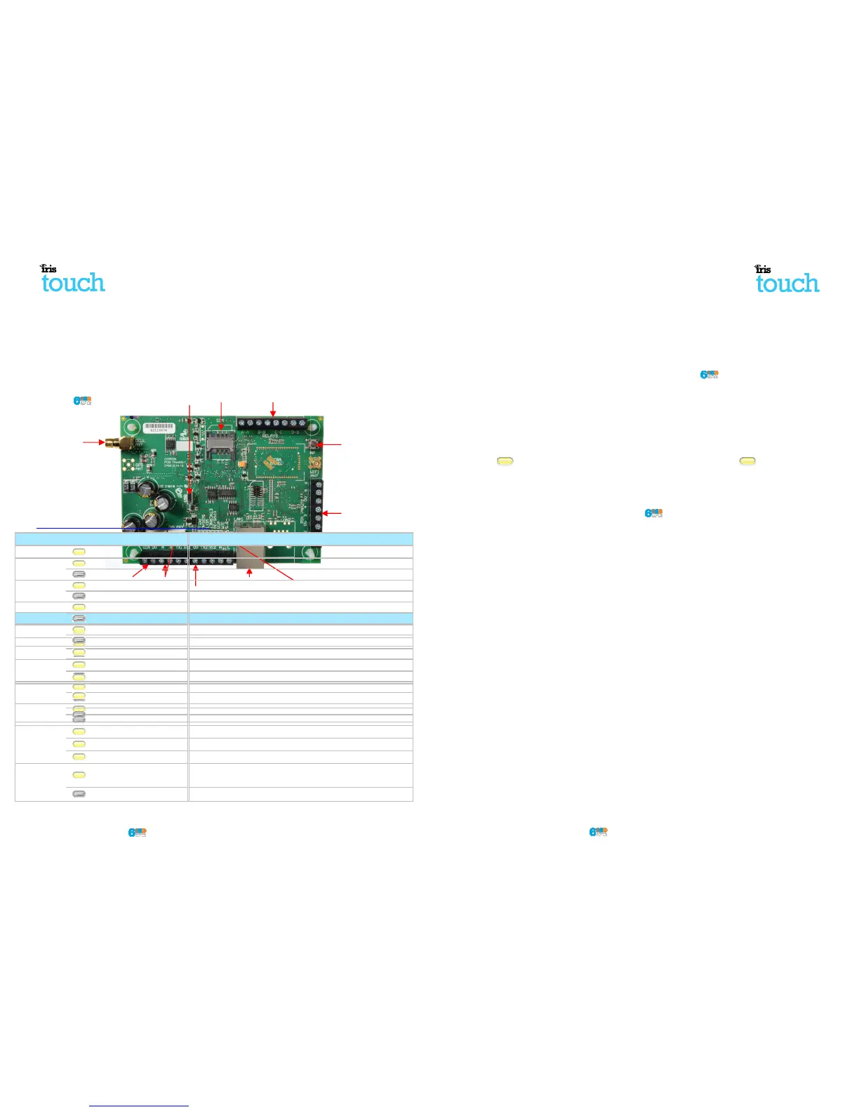
4. Board Configuration
IRIS Touch
LEDS
LED & Colour Indication
SYS Flashing 0.5s on, 0.5s Off Shows dialler is operational
SIM
Dialler is seeing the SIM card
Dialler not currently seeing the SIM card
GSM connected / registered (IRIS Touch 600 & 640)
GSM Not connected / registered (IRIS Touch 600 & 640)
GPRS/3G is attached to the network (IRIS Touch 600 & 640)
GPRS/3G is not attached to the network (IRIS Touch 600 & 640)
ETH connected / synchronized (IRIS Touch 620
ETH disconnected / not synchronized (IRIS Touch 620 & 640)
SERIAL
Flashing 0.2s On, 0.2s Off
Shows not communicating with panel
Flashing 1.5s On, 1.5s Off Shows dialler not configured
Flashing 0.1s On, 0.9s Off Shows normal communication
POLL
On
Successfully polling with m
Flickers off to show each poll
Off
Not polling with monitoring centre
Dialler not currently seeing the SIM card
GSM connected / registered (IRIS Touch 600 & 640)
GSM Not connected / registered (IRIS Touch 600 & 640)
GPRS/3G is attached to the network (IRIS Touch 600 & 640)
GPRS/3G is not attached to the network (IRIS Touch 600 & 640)
ETH connected / synchronized (IRIS Touch 620
ETH disconnected / not synchronized (IRIS Touch 620 & 640)
Shows not communicating with panel
Flickers off to show each poll
AP
button
IRIS Touch Quick Installation & Maintenance Guide
6.10. Testing
Once all configurations are complete perform a full commissioning test with the m
will normally involve testing normal alarm transmissions
from the alarm panel to the monitoring
and verifying that these are successfully received.
7. Maintenance
There is no requirement for any onsite maintenance on the IRIS Touch .
If engineers want to carry out a maintenance inspe
ction please perform the following:
• Confirm the status of the IRIS Touch unit.
• Clear any faults on the dialler.
•
Perform full test of alarms from the alarm panel and confirm these are received at the
monitoring centre.
The IRIS Touch will give a visual indication of the current sy
stem status via the SYS LED
constant the current setup of the dialler is all reporting OK, if yellow flashing
some trouble events being reported?
7.1. Confirm current status
The IRIS Touch will indicate the current status via the LEDs as per the information
For further information please refer to the IRIS Touch
Engineer Manual available from
http://www.chironsc.com/downloads_security.html.
LED & Colour Indication
SYS Flashing 0.5s on, 0.5s Off Shows dialler is operational
SIM
Dialler is seeing the SIM card
Dialler not currently seeing the SIM card
GSM connected / registered
GSM Not connected / registered (IRIS Touch 600 & 640)
GPRS/3G is attached to the network (IRIS Touch 600 & 640)
GPRS/3G is not attached to the network (IRIS Touch 600 & 640)
synchronized (IRIS Touch 620 & 640)
ETH disconnected / not synchronized (IRIS Touch 620 & 640)
SERIAL
Flashing 0.2s On, 0.2s Off
Shows not communicating with panel
Flashing 1.5s On, 1.5s Off Shows dialler not configured
Flashing 0.1s On, 0.9s Off Shows normal communication
POLL
On
Successfully polling with monitoring centre
Flickers off to show each poll
Off
Not polling with monitoring centre
7.2. Communication paths check and communication to ARC
Engineers can test the communication
paths for both polling and alarm communications
of the communication paths (dual path), and then confirming
that the polling LED stays on for a number of
minutes. Next the engineer would
send an alarm from the alarm panel and confirm this
at the monitoring centre.
If you have an IRIS Touch 640 with dual paths enabled repeat these tests
for the other communication
path.
If all working correctly you will then receive confirmation that you can leave site.
from the alarm panel to the monitoring
ction please perform the following:
Perform full test of alarms from the alarm panel and confirm these are received at the
stem status via the SYS LED
. If this is yellow
the dialler has
Engineer Manual available from
Dialler not currently seeing the SIM card
GSM Not connected / registered (IRIS Touch 600 & 640)
GPRS/3G is attached to the network (IRIS Touch 600 & 640)
GPRS/3G is not attached to the network (IRIS Touch 600 & 640)
synchronized (IRIS Touch 620 & 640)
ETH disconnected / not synchronized (IRIS Touch 620 & 640)
Shows not communicating with panel
Successfully polling with monitoring centre
Flickers off to show each poll
paths for both polling and alarm communications
that the polling LED stays on for a number of
send an alarm from the alarm panel and confirm this
for the other communication