Page 8 of 16 IRIS Touch Quick Installation & Maintenance Guide Version 1.1
6.5. PIN Inputs
The IRIS Touch dialler has 6 Pin inputs that can be used to generate alarm
• Text messages via SMS (GSM &GPRS.)
• SIA, Contact ID or Fast Format alarm messages over IP to the monitoring c
Note: These pin alarm inputs can also be used when the dialler is directly connected to an alarm panel
via the serial or RS485 connections.
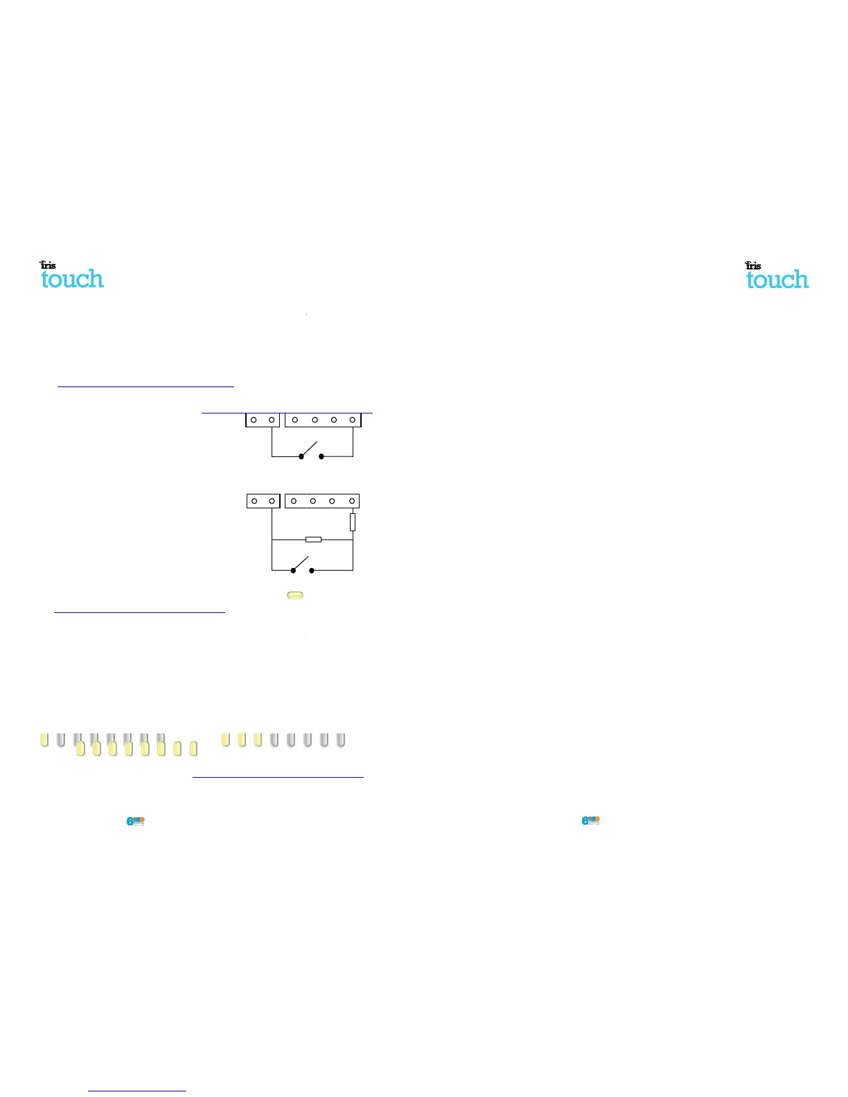
Via Open/Close Contact Source
Each PIN input is designed to be connected in a loop via
an open/close contact source from an alarm panel, or
other device, to a reference ground PIN available on the
IRIS dialler, as shown opposite.
Opening the contact (i.e. loop is open circuit) generates
an alarm signal. Closing the contact generates the
equivalent restore signal.
Via Sense Resistors
It is also possible to link the contacts to the IRIS dialler via
sense resistors so that an open or short circuit tamper on
the loop can be detected and the monitoring centre
alerted. In this case, the connections should be made as
shown opposite.
Note: For this feature to work correctly it is essential that
the resistors are connected at the contact end of the loop
and not the dialler end. The monitoring centre must also
enable the monitoring of this facility on the dialler within
the IRIS Secure Apps receiving system.
6.6. Switch on and test
To confirm power is applied, look for the indicator SYS LED is flashing Yellow
board.
6.7. GPRS Network Scan (IRIS Touch 600 or 640)
With the IRIS Touch 600 or 640 that are using the GPRS communication you will need to perform a signal
strength check, to confirm that in the current installation you have the required signal strength for a
reliable connection.
GPRS signal strength
Press and hold the “AP” button which will allow you
to see the current signal strengt
For a reliable GPRS connection it is recommended that you have a signal strength of 3 or more LED
shown on the examples below:
Signal strength too low Minimum signal strength
If the signal strength is below or close to minimum then try to reposition the antenna or use an external
high gain antenna to improve signal strength (if necessary)
and rerun the signal strength test to gain best
signal strength.
Once you have the required GPRS signal strength
you can then move onto the configuration
Note: These pin alarm inputs can also be used when the dialler is directly connected to an alarm panel
With the IRIS Touch 600 or 640 that are using the GPRS communication you will need to perform a signal
strength check, to confirm that in the current installation you have the required signal strength for a
to see the current signal strengt
For a reliable GPRS connection it is recommended that you have a signal strength of 3 or more LED
If the signal strength is below or close to minimum then try to reposition the antenna or use an external
and rerun the signal strength test to gain best
you can then move onto the configuration
Pin inputs
IRIS Touch Quick Installation & Maintenance Guide
6.8. Configuration
To configure your dialler, use one of the following methods:
• Alarm panel integration e.g. Honeywell Galaxy
(RS485 connection) Texecom Premier range (RS232
TTL connection). Please refer to Section 6.9 “Panel configuration”.
Note: For connections to Honeywell Galaxy or Texecom Premier on the serial integration ensure
you configure the alarm panel first as this will transmit
configuration to the IRIS
For more details on the alarm panel integration download the fu
ll panel installation manual from
http://www.chironsc.com/downloads_security.html.
• Connect the board’s Micro
USB connector to a laptop / PC running the IRIS Toolbox software
Download the IRIS ToolBox user guide from
http://www.chironsc.com/downloads_security.html
Note: If you want to use the IRIS Touch dialler for pin inputs only and no s
need to connect a Laptop / PC and configure the d
ialler using the IRIS Toolbox software
remote Touch screen and Installation Wizard.
Defaulting
If at any point you want to completely default the dia
ller you can use the following p
1. Push and hold down the AP button.
2. Then completely power down the IRIS Touch
whilst still holding the AP button.
3. Now reapply power and whilst still keeping
the AP button pushed down for another 10 seconds.
6.9. Panel configuration
IRIS Touch 6xx diallers can be configured directly
by the integration with certain panel manufacture
this is detailed below:
Configuration on Honeywell Galaxy Panel via RS485
The IRIS Touch dialler can simulate a Galaxy Ethernet Module (Comm’
s Mod 4) and remote keypad,
both Alarms and Remote Service Suite upload/download connection. For further information on both the
Galaxy installation and Remote Service Suite upload/download connection please refer to the IRIS
Honeywell Installation manual or IRIS Remote Service
App Client User Guide for Honeywell Galaxy range
from http://www.chironsc.com/downloads_security.html.
Note: For GPRS it is not possible to configure the settings (e.g. APN) from the Galaxy
Galaxy has no entry method.
IRIS Touch 600 or 640 with GPRS connection:
The GPRS APN can be configured via an SMS message from any mobile phone.
Connect the IRIS Touch dialler to the Galaxy Data bus as indicated in Section 6.3 “
power up the Galaxy Control panel, if not already powered.
If GPRS is used, you will need to set the GPRS APN. You can do this by sending
a text message to the phone
number of the SIM card being used. The text should be in the format:
AT%G10=’apn’
Where ‘apn’ is the APN name, e.g. ‘orangeinternet’
Note: The APN must be configured before the IRIS Touch is polling as after the dialler is polling all SMS
configuration will be rejected for security.
Alternatively, the information can be set via the IR
IS Toolbox software on a PC / Laptop which connects via
the Micro USB connector. This is available from
http://www.chironsc.com/downloads_security.html
(RS485 connection) Texecom Premier range (RS232
Note: For connections to Honeywell Galaxy or Texecom Premier on the serial integration ensure
configuration to the IRIS
ll panel installation manual from
USB connector to a laptop / PC running the IRIS Toolbox software
http://www.chironsc.com/downloads_security.html
ialler using the IRIS Toolbox software
ller you can use the following p
whilst still holding the AP button.
the AP button pushed down for another 10 seconds.
by the integration with certain panel manufacture
s Mod 4) and remote keypad,
both Alarms and Remote Service Suite upload/download connection. For further information on both the
Galaxy installation and Remote Service Suite upload/download connection please refer to the IRIS
App Client User Guide for Honeywell Galaxy range
Note: For GPRS it is not possible to configure the settings (e.g. APN) from the Galaxy
a text message to the phone
Note: The APN must be configured before the IRIS Touch is polling as after the dialler is polling all SMS
IS Toolbox software on a PC / Laptop which connects via
http://www.chironsc.com/downloads_security.html
 Loading...