EasyManua.ls Logo

Christie Cinema 4K-RGB CP4315-RGB User Manual

Christie Cinema 4K-RGB CP4315-RGB
97 pages
To Next Page IconTo Next Page
Page #1 background imageLoading...
Page #1 background image
Service Guide
020-102713-03
Cinema 4K-RGB
CP4315-RGB, CP4320-RGB, CP4325-RGB, CP4330-
RGB

Table of Contents

Question and Answer IconNeed help?

Do you have a question about the Christie Cinema 4K-RGB CP4315-RGB and is the answer not in the manual?

Christie Cinema 4K-RGB CP4315-RGB Specifications

General IconGeneral
BrandChristie
ModelCinema 4K-RGB CP4315-RGB
CategoryProjector
LanguageEnglish

Summary

Notices

Copyright and General Information

Copyright notice, general disclaimer, and product changes.

Warranty and Maintenance

Details warranty terms, exclusions, and preventative maintenance requirements.

Regulatory and Environmental Compliance

Covers regulatory compliance and environmental disposal guidelines.

Introduction

Site and Environment Requirements

Specifies installation location, environment, and power connection needs.

Projector Components (Front)

Front Component Identification

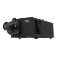
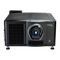
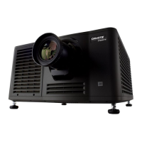
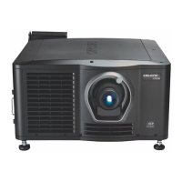
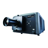
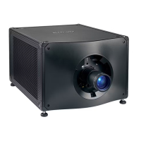
Identifies lens, feet, access door, and communication panel.

Projector Components (Rear)

Rear Component Identification

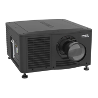
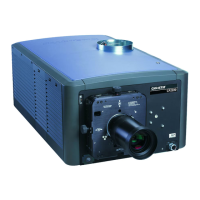
Identifies touch panel, AC breakers, air exhaust, power, and air intake.

Security Roles

Theatre Personnel Responsibilities

Defines roles for theatre personnel in diagnostics and system security.

Product Documentation

Model-Specific Documentation Access

Provides links and QR codes for accessing documentation for specific models.

Related Documentation

Additional Product Manuals

Lists other relevant manuals like Installation, User, Safety, and Specifications guides.

Service Guidelines

Ordering Parts and Replacing Modules

Guidelines for ordering parts and correctly replacing projector modules.

Interconnections, Line Drawings, and Live Servicing

Information on diagrams and safety for servicing energized equipment.

Safety Precautions

General Safety Precautions

Essential safety guidelines for operating and servicing the projector safely.

Laser and AC Power Safety

Laser Safety Precautions

Critical safety information regarding laser hazards and operation.

AC Power Precautions

Safety guidelines for connecting and working with AC power.

Light Intensity Hazard Distance

Hazard Distances by Projection Lens

CP4315/4320/4330-RGB Hazard Distances

Table of laser hazard distances for specific projection lenses.

CP4325-RGB Hazard Distances

Table of laser hazard distances for CP4325-RGB projectors.

Market-Specific Hazard Distances and Installation

Other Markets Hazard Distances

Hazard distances based on IEC standards for non-US markets.

US Installation Requirements

Specific requirements for laser projector installations in the United States.

Product Labels and General Hazards

Product Labels Overview

Information about the labels used on the product.

Fire, Shock, and Electrical Hazards

Warnings and precautions related to fire, shock, and electrical hazards.

General Hazards and Mandatory Actions

Moving Parts, Fan, and Voltage Hazards

Warnings regarding hazards from moving parts, fans, and voltage.

Mandatory Safety Actions

Crucial steps like consulting the manual and disconnecting power.

Electrical Labels and Hazard Symbols

Identification of electrical labels and hazard symbols.

Laser and High Leakage Hazard Warnings

CP4330-RGB FDA Laser Variance

FDA laser variance information for US CP4330-RGB projectors.

Light and High Leakage Current Warnings

Warnings about light hazards, eye damage, and leakage current.

Service Setups Overview

Turning Projector On/Off

Procedures for powering the projector on and off.

Calibrating Intelligent Lens System

Steps to calibrate the Intelligent Lens System for optimal performance.

Adjusting Boresight

Guide for adjusting boresight to compensate for screen tilt.

Adjusting Boresight

Boresight Adjustment Procedure and Controls

Steps and controls for performing boresight adjustments using test patterns.

Adjusting Boresight

Horizontal and Vertical Boresight Adjustments

Detailed steps for horizontal and vertical boresight adjustments.

Locking Boresight Screws

Procedure for locking the boresight adjustment screws.

Adjusting Integrator Rod and Fold Mirror

Adjusting Integrator Rod and Fold Mirror

Integrator Rod Adjustment Steps

Steps for adjusting the integrator rod zoom and focus.

Fold Mirror Adjustment Steps

Steps for adjusting the fold mirror.

Adjusting Integrator Rod and Fold Mirror

Fold Mirror Horizontal and Vertical Adjustment

How to make horizontal and vertical adjustments on the fold mirror.

Adjusting DMD Convergence

Adjusting Integrator Rod and Fold Mirror

Illumination Spot Adjustment

Adjusting the illumination spot for optimal DMD coverage.

Adjusting DMD Convergence

Convergence Adjustment Procedure and Knobs

Steps for adjusting convergence using test patterns and related knobs.

Adjusting LOS Coupling Mirror

Replacing or Refilling Coolant

Removing the Coolant Reservoir

Parts and Module Replacement

Tools Required and Maintenance Prerequisites

List of tools and essential tasks before performing projector maintenance.

Index of Parts and Modules

Parts List Continuation

Parts List Continuation

Lens Mount Components

Removing Projection Lens and Replacing Lens Mount

Steps for removing the lens and replacing the lens mount.

Lens Mount Components

Lens Mount Removal Steps

Steps for removing the lens mount, including harness and screws.

Lens Mount Components

Removing Lens Mount from Projector Head

Final steps to remove the lens mount and notes on new mount installation.

Filtration

Replacing Light Engine Compartment Air Filter

Step-by-step guide to replacing the air filter in the light engine compartment.

Filtration

Replacing Main Intake Air Filter

Instructions for replacing the main air intake filter of the projector.

Projector Covers and Feet

Removing the Top Cover

Detailed steps for removing the projector's top cover.

Projector Covers and Feet

Removing Touch Panel and Rear Cover

Procedures for removing the touch panel and the rear cover.

Projector Covers and Feet

Removing Rear Cover Continuation and Electronics-Side Cover

Final steps for rear cover removal and steps for electronics-side cover.

Projector Covers and Feet

Removing Front Cover and Side-Intake Cover

Steps for removing front cover and side-intake cover.

Projector Covers and Feet

Removing Side-Intake Cover Continuation and Bottom Cover

Final steps for side-intake cover and steps for bottom cover removal.

Projector Covers and Feet

Removing Bottom Cover Continuation

Final steps for bottom cover removal and installation.

Electronics

Servicing the Card Cage

Steps for accessing and servicing the projector's card cage.

Electronics

Servicing Card Cage Continuation and Removing AC Breaker

Final card cage steps and procedure for removing the AC breaker.

Electronics

Removing AC Breaker Continuation and Replacing Power Supplies

Final AC breaker steps and guide for replacing power supplies.

Electronics

Replacing Power Supplies Continuation

Steps for disconnecting DC output cables and fasteners for power supply replacement.

Electronics

Replacing Power Supplies Continuation

Final steps for power supply replacement, including support bracket and torque specifications.

Electronics

Power Supply DC Output Terminals

Diagrams showing 12V and 48V DC output terminal configurations.

Electronics

Removing the Laser Driver Card Cage

Procedure for removing the laser driver card cage.

Electronics

Removing Laser Driver Card Cage Continuation

Final steps for laser driver card cage removal and re-installation.

Electronics

Replacing Temperature Sensor and SID Harness

Steps for replacing the temperature sensor and the SID harness.

Electronics

Replacing Mini-SAS Cables

Procedure for replacing the mini-SAS data cables.

Ventilation and Cooling

Replacing Card Cage and Blue Formatter Fans

Steps to replace card cage intake fan and blue formatter fan.

Ventilation and Cooling

Replacing Blue/Green Formatter Fans

Final steps for blue fan and steps for replacing green formatter fan.

Ventilation and Cooling

Replacing Green/Red Formatter Fans

Final steps for green fan and steps for replacing red formatter fan.

Ventilation and Cooling

Replacing Red Formatter Fan Continuation and Card Cage Exhaust Fan

Final red fan steps and replacing card cage exhaust fan.

Ventilation and Cooling

Replacing Card Cage Exhaust Fan Continuation and Radiator Intake Fans

Final card cage fan steps and replacing radiator intake fans.

Replacing Laser Driver Card Cage Fans

Steps to replace fans within the laser driver card cage.

Ventilation and Cooling

Replacing Laser Driver Card Cage Fans Continuation and Light Engine Intake Fans

Final laser driver fan steps and replacing light engine intake fans.

Ventilation and Cooling

Replacing Light Engine Intake Fans Continuation

Final steps for light engine intake fan replacement.

Ventilation and Cooling

Removing Coolant Reservoir and Pump Module

Steps to remove coolant reservoir and pump module.

Ventilation and Cooling

Removing Pump Module Continuation and Replacing Radiator

Final pump module steps and replacing radiator.

Ventilation and Cooling

Replacing Radiator Continuation

Steps for disconnecting hoses and removing the radiator.

Ventilation and Cooling

Replacing Radiator Continuation, Relief Tank, and Exhaust Duct

Final radiator steps, relief tank info, and exhaust duct replacement.

Ventilation and Cooling

Replacing Exhaust Duct Continuation

Final steps for exhaust duct replacement.

Optics

Replacing the Integrator Assembly

Procedure to replace the integrator assembly which combines laser light.

Optics

Replacing Integrator Assembly Continuation

Final steps for integrator assembly removal and re-installation.

Optics

Replacing Integrator Assembly Continuation and Fold Mirror Adjust

Final integrator steps and adjusting the fold mirror.

Optics

Replacing Fold Mirror Adjust Continuation and Light Dump

Final fold mirror steps and replacing the light dump.

Optics

Replacing Light Dump Continuation and Light Engine

Final light dump steps and replacing the light engine.

Optics

Replacing Light Engine Continuation and Packing Light Engine

Steps for removing light engine and packing for shipping.

Optics

Packing Light Engine Continuation

Final steps for packing the light engine, including securing and zip ties.

Optics

Packing Light Engine Continuation

Final steps for packing the light engine into ESD bag and shipping box.

Optics

Packing Light Engine Continuation and LOS Coupling Elbow

Final packing steps and replacing the LOS coupling elbow.

Optics

Replacing LOS Coupling Elbow Continuation and Mirror Assembly Removal

Final LOS elbow steps and removing mirror assembly.

Optics

Replacing the Shutter

Procedure for replacing the shutter component.

Printed Circuit Boards and Sensors

Replacing F-Main Electronics Card

Steps to replace the primary input panel of the projector.

Printed Circuit Boards and Sensors

Replacing F-Main Electronics Card Continuation and IMB

Final F-Main steps and procedure for replacing the IMB.

Printed Circuit Boards and Sensors

Replacing IMB Continuation and Housekeeping Board (HKBB)

Final IMB steps and replacing the housekeeping board.

Printed Circuit Boards and Sensors

Replacing Housekeeping Board (HKBB) Continuation and SCCB

Final HKBB steps and procedure for replacing the SCCB.

Printed Circuit Boards and Sensors

Replacing SCCB Continuation and HUB-NX

Final SCCB steps and procedure for replacing the HUB-NX.

Printed Circuit Boards and Sensors

Replacing HUB-NX Continuation and DTSM

Final HUB-NX steps and replacing the dual temperature sensor module.

Printed Circuit Boards and Sensors

Replacing DTSM Continuation and Status LED Board (SLB)

Final DTSM steps and replacing the status LED board.

Printed Circuit Boards and Sensors

Replacing SLB Continuation and LVCS Board

Final SLB steps and replacing the low voltage current source board.

Printed Circuit Boards and Sensors

Replacing LVCS Board Continuation and HVCS Boards

Final LVCS steps and replacing high voltage current source boards.

Printed Circuit Boards and Sensors

Replacing HVCS Boards Continuation and LBP7 Board

Final HVCS steps and replacing the laser backplane board.

Printed Circuit Boards and Sensors

Replacing LBP7 Board Continuation, DIB PCB, and Color Sensor Board

Final LBP7 steps, DIB PCB, and color sensor board replacement.

Printed Circuit Boards and Sensors

Replacing Color Sensor Board Continuation

Steps for removing the color sensor housing and replacing the fold mirror.

Printed Circuit Boards and Sensors

Replacing Color Sensor Board Continuation and Harness

Final color sensor steps and replacing its harness.

Printed Circuit Boards and Sensors

Replacing Color Sensor Board Harness Continuation

Steps for detaching the sensor board and disconnecting its harness.

Printed Circuit Boards and Sensors

Replacing Color Sensor Board Harness Continuation and DAC Calibration

Final harness steps and procedure for DAC calibration.

Printed Circuit Boards and Sensors

Performing DAC Calibration Continuation and LiteLOC v1 Calibration

Final DAC steps and procedure for LiteLOC v1 calibration.

Printed Circuit Boards and Sensors

Performing LiteLOC v1 Calibration Continuation

Steps for executing scripts and setting values for LiteLOC calibration.

Printed Circuit Boards and Sensors

Performing LiteLOC v1 Calibration Continuation

Final steps for LiteLOC calibration, including temperature acclimatization and reboot.

Corporate Offices

Worldwide Offices

Independent Sales Consultant Offices

Related product manuals