This document outlines the installation and adjustment procedures for the Christie ultra short throw (UST) lens, designed to position a projector as close as possible to the screen.
Function Description
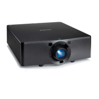
The Christie ultra short throw lens is an accessory for specific Christie HS Series 2K and 4K projectors, enabling them to project a large image from a very short distance. This is particularly useful in environments with limited space or where the projector needs to be unobtrusive. The installation process involves mounting a dedicated lens support bracket to the projector, attaching the UST lens, and then performing several calibration and adjustment steps to ensure optimal image quality and alignment.
Important Technical Specifications
The UST lens is compatible with the following Christie projector models:
- D13HD2-HS
- D13WU2-HS
- D16HD-HS
- D16WU-HS
- D20HD-HS
- D20WU-HS
- Christie 4K7-HS
- Christie 4K10-HS
Required components for installation include:
- UST lens bracket kit (P/N: 003-006916-XX)
- 3 mm Allen key
- 5 mm Allen key
- 6 mm Allen key
- Hexagon wrench
The lens holders are replaceable and are marked with an "A" for HS Series 2K models and a "T" for 4K7-HS and 4K10-HS models, indicating specific bracket compatibility. The installation involves various screws: M4 x L22, M8 x 16, and M4 x L10, which are tightened and sometimes loosened by one turn during the process to allow for adjustments.
Usage Features
The primary usage feature of the UST lens is its ability to project from an extremely close distance, offering flexibility in projector placement. The installation process is detailed, ensuring proper alignment and secure mounting.
Mounting the Lens Support Bracket:
- Initial Lens Calibration: Before mounting, the projector must undergo a lens calibration. If a standard lens is installed, this is done via the projector's on-screen menu (Menu > Configuration > Lens Settings > Lens Calibration). If no non-UST lens is present, calibration is performed by connecting to the projector via RS232 or Ethernet (default IP 192.168.0.100) and sending the serial API command
LCB+HOME 1.
- Preparation: The projector is turned off, and any existing non-UST lens is removed.
- Bracket Alignment: Mark lines on the bracket must be aligned before mounting.
- Screw Adjustment: Two M4 x L22 screws are initially tightened and then loosened by one turn to facilitate later adjustments.
- Support Base Installation: The projector is flipped onto its top side. The support base (without the lens bracket attached) is secured to the projector. For HS Series 2K, two M8 x 16 screws and washers are used, with the front screw hooking the projector's front cover. For 4K7-HS and 4K10-HS models, four M8 x 16 screws and washers are used at the front position.
- Lens Installation: The projector is flipped back over, and the ultra short throw lens is installed.
- Lens Bracket Attachment: The lens bracket is attached to the support base using a location hole (A) and pin (B). Specific brackets (marked "A" for HS Series 2K, "T" for 4K7-HS/4K10-HS) must be used.
- Final Bracket Securing: M4 x L10 screws (A for HS Series 2K, T for 4K7-HS/4K10-HS) are tightened until snug and then loosened by one turn.
- Lens Bracket Shift: The lens bracket is shifted to fit the L-UST lens neck, ensuring the lens bracket plate (A) does not tilt with the lens holder (B).
- Lens Fixture Securing: Two M4 x L10 screws secure the lens fixture to the lens bracket.
- Screw Tightening: The M4 x L10 screws from step 8 and the M4 x L22 screws from step 4 are tightened.
Adjusting the Ultra Short Throw Lens:
- Power On: The projector is powered on.
- Initial Screw Loosening: Two M4 x L22 screws are loosened by one turn.
- Lens Calibration: A lens calibration is performed.
- Image Position Adjustment: The Lens Shift function is used to adjust the image position. It is crucial not to use Lens Shift when the M4 x L22 screws are locked.
- Screw Tightening: The M4 x L22 screws are tightened. If the lens tilt is significant, the lens should be gently lifted to reduce image offset before locking the screws.
- Fine-tuning Image Position: Two M6 screws are adjusted for fine-tuning the image position.
- Lens Roll Angle Adjustment: An M6 screw is adjusted using a hexagon wrench to fine-tune the lens roll angle.
- Boresight Adjustment: Two M4 screws on the lens supporter are loosened by one turn. The boresight is adjusted (refer to the product's Installation and Setup guide for details).
- Final Screw Tightening: The two M4 screws from step 8 are tightened.
- Lens Motor Lock: To prevent accidental changes, the Lens Shift function is locked via the on-screen display (Configuration > Lens setting > Lock all Lens Motors > Locked).
Maintenance Features
The document primarily focuses on installation and initial adjustment, rather than ongoing maintenance. However, the use of specific tools (Allen keys, hexagon wrench) and the detailed step-by-step instructions imply that the installation and adjustment process is designed to be precise and repeatable. The locking mechanism for lens motors after boresight adjustment serves as a preventative measure to maintain calibration and reduce the need for frequent re-adjustments. The replaceable nature of the lens holders (marked A or T) suggests that these components can be serviced or replaced if necessary, though specific maintenance procedures for them are not detailed in this document.
Technical support is available globally for assistance with Christie products, including this UST lens. Contact information is provided for North and South America, Europe, Middle East, Africa, and Asia Pacific regions (Australia, China, India, Japan, Singapore, and South Korea), as well as Christie Professional Services. This ensures that users can obtain expert help for any issues encountered during installation, adjustment, or operation.